Optimizing Automated Test Applications for Multicore Processors with NI LabVIEW
Overview
Multicore Programming Fundamentals White Paper Series

Multicore Programming Fundamentals White Paper Series
LabVIEW provides a unique and easy-to-use graphical programming environment for automated test applications. However, it is its ability to dynamically assign code to various CPU cores that improves execution speeds on multi-core processors. Learn how LabVIEW applications can be optimized to take advantage of parallel programming techniques.
Contents
- The Challenge of Multi-Threaded Programming
- Implementing Parallel Test Algorithms
- Configuring Custom Parallel Test Algorithms
- Optimizing Hardware-in-the-Loop Applications
- Conclusion
- More Resources on Multicore Programming
The Challenge of Multi-Threaded Programming
Until recently, innovations in processor technology have resulted in computers with CPUs that operate at higher clock rates. However, as clock rates approach their theoretical physical limits, companies are developing new processors with multiple processing cores. With these new multicore processors, engineers developing automated test applications can achieve the best performance and highest throughput by using parallel programming techniques. Dr. Edward Lee, an electrical and computer engineering professor at the University of California - Berkeley, describes the benefits of parallel processing.
“Many technologists predict that the end of Moore’s Law will be answered with increasingly parallel computer architectures. If we hope to continue to get performance gains in computing, programs must be able to exploit this parallelism.”
Moreover, industry experts recognize that it is a significant challenge for programming applications to take advantage of multicore processors. Bill Gates, founder of Microsoft, Inc., explains.
“To fully exploit the power of processors working in parallel…software must deal with the problem of concurrency. But as any developer who has written multithreaded code can tell you, this is one of the hardest tasks in programming.”
Fortunately, NI LabVIEW software offers an ideal multicore processor programming environment with an intuitive API for creating parallel algorithms that can dynamically assign multiple threads to a given application. In fact, you can optimize automated test applications using multicore processors to achieve the best performance.
Moreover, PXI Express modular instruments enhance this benefit because they take advantage of the high data transfer rates possible with the PCI Express bus. Two specific applications that benefit from multicore processors and PXI Express instruments are multichannel signal analysis and in-line processing (hardware in the loop). This white paper evaluates various parallel programming techniques and characterizes the performance benefits that each technique produces.
Implementing Parallel Test Algorithms
One common automated test application that benefits from parallel processing is multichannel signal analysis. Because frequency analysis is a processor-intensive operation, you can improve execution speed by running test code in parallel so that each channel’s signal processing can be distributed to multiple processor cores. From a programmer’s perspective, the only change you need to make to gain this benefit is a minor restructuring of the test algorithm.
To illustrate, compare the execution times of two algorithms for multichannel frequency analysis (fast Fourier transform, or FFT) on two channels of a high-speed digitizer. The NI PXIe-5122 14-bit high-speed digitizer uses two channels to acquire signals at the maximum sample rate (100 MS/s). First, examine the traditional sequential programming model for this operation in LabVIEW.
Figure 1. LabVIEW code utilizes sequential execution.
In Figure 1, frequency analysis of both channels is performed in an FFT Express VI, which analyzes each channel in series. While the algorithm shown above can still be executed efficiently in multicore processors, you can improve algorithm performance by processing each channel in parallel.
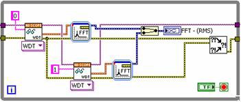
If you profile the algorithm, you notice that the FFT takes considerably longer to complete than the acquisition from the high-speed digitizer. By fetching each channel one at a time and performing two FFTs in parallel, you can significantly reduce the processing time. See Figure 2 for a new LabVIEW block diagram that uses the parallel approach.
Figure 2. LabVIEW code utilizes parallel execution.
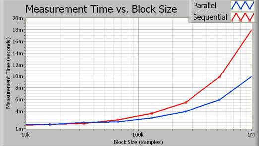
Each channel is fetched from the digitizer sequentially. Note that you could perform these operations completely in parallel if both fetches were from unique instruments. However, because an FFT is processor-intensive, you can still improve performance simply by running the signal processing in parallel. As a result, the total execution time is reduced. Figure 3 shows the execution time of both implementations.
Figure 3. As the block size increases, the processing time saved through parallel execution becomes more obvious.
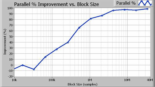
In fact, the parallel algorithm approaches a two times performance improvement for larger block sizes. Figure 4 illustrates the exact percent increase in performance as a function of acquisition size (in samples).
Figure 4. For block sizes greater than 1 million samples (100 Hz resolution bandwidth), the parallel approach results in an 80 percent or better performance increase.
Increasing the performance of automated test applications is easy to achieve on multicore processors because you allocate each thread dynamically using LabVIEW. In fact, you are not required to create special code to enable multithreading. Instead, parallel test applications benefit from multicore processors with minimal programming adjustments.
Configuring Custom Parallel Test Algorithms
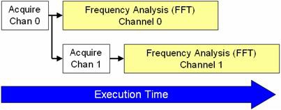
Parallel signal processing algorithms help LabVIEW divide processor usage among multiple cores. Figure 5 illustrates the order in which the CPU processes each part of the algorithm.
Figure 5. LabVIEW can process much of the acquired data in parallel, saving execution time.
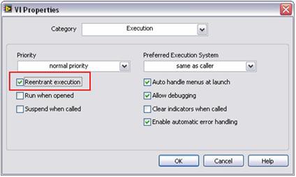
Parallel processing requires LabVIEW to make a copy (or clone) of each signal processing subroutine. By default, many LabVIEW signal processing algorithms are configured to have “reentrant execution.” This means that LabVIEW dynamically allocates a unique instance of each subroutine, including separate threads and memory space. As a result, you must configure custom subroutines to operate in a reentrant fashion. You can do this with a simple configuration step in LabVIEW. To set this property, select File >> VI Properties and choose the Execution category. Then, select the Reentrant execution flag as shown in Figure 6.
Figure 6. With this simple step, you can execute multiple custom subroutines in parallel, just like standard LabVIEW analysis functions.
As a result, you can achieve improved performance in your automated test applications on multicore processors by using simple programming techniques.
Optimizing Hardware-in-the-Loop Applications
A second application that benefits from parallel signal processing techniques is the use of multiple instruments for simultaneous input and output. In general, these are referred to as hardware-in-the-loop (HIL) or in-line processing applications. In this scenario, you may use either a high-speed digitizer or high-speed digital I/O module to acquire a signal. In your software, you perform a digital signal processing algorithm. Finally, the result is generated by another modular instrument. A typical block diagram is illustrated in Figure 7.
Figure 7. This diagram shows the steps in a typical hardware-in-the-loop (HIL) application.
Common HIL applications include in-line digital signal processing (such as filtering and interpolation), sensor simulation, and custom component emulation. You can use several techniques to achieve the best throughput for in-line digital signal processing applications.
In general, you can use two basic programming structures – the single-loop structure and the pipelined multiloop structure with queues. The single-loop structure is simple to implement and offers low latency for small block sizes. In contrast, multiloop architectures are capable of much higher throughput because they better utilize multicore processors.
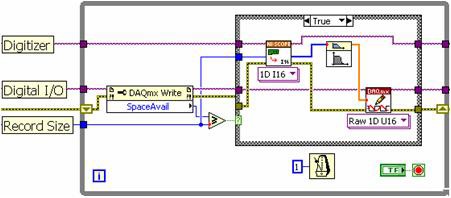
Using the traditional single-loop approach, you place a high-speed digitizer read function, signal processing algorithm, and high-speed digital I/O write function in sequential order. As the block diagram in Figure 8 illustrates, each of these subroutines must execute in a series, as determined by the LabVIEW programming model.
Figure 8. With the LabVIEW single-loop approach, each subroutine must execute in series.
The single-loop structure is subject to several limitations. Because each stage is performed in a series, the processor is limited from performing instrument I/O while processing the data. With this approach, you cannot efficiently use a multicore CPU because the processor only executes one function at a time. While the single-loop structure is sufficient for lower acquisition rates, a multiloop approach is required for higher data throughput.
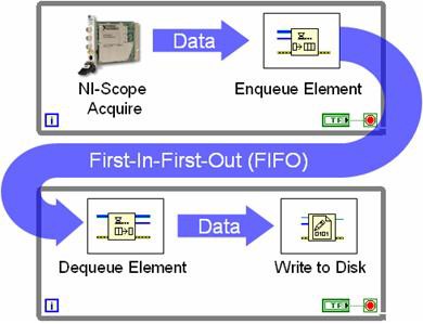
The multiloop architecture uses queue structures to pass data between each while loop. Figure 9 illustrates this programming between while loops with a queue structure.
Figure 9. With queue structures, multiple loops can share data.
Figure 9 represents what is typically referred to as a producer-consumer loop structure. In this case, a high-speed digitizer acquires data in one loop and passes a new data set to the FIFO during each iteration. The consumer loop simply monitors the queue status and writes each data set to disk when it becomes available. The value of using queues is that both loops execute independently of one another. In the example above, the high-speed digitizer continues to acquire data even if there is a delay in writing it to disk. The extra samples are simply stored in the FIFO in the meantime. Generally, the producer-consumer pipelined approach provides greater data throughput with more efficient processor utilization. This advantage is even more apparent in multicore processors because LabVIEW dynamically assigns processor threads to each core.
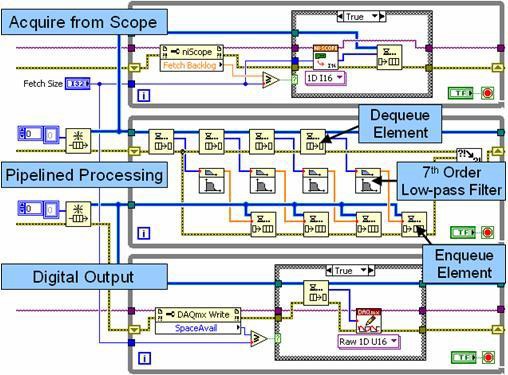
For an in-line signal processing application, you can use three independent while loops and two queue structures to pass data among them. In this scenario, one loop acquires data from an instrument, one performs dedicated signal processing, and the third writes data to a second instrument.
Figure 10. This block diagram illustrates pipelined signal processing with multiple loops and queue structures.
In Figure 10, the top loop is a producer loop that acquires data from a high-speed digitizer and passes it to the first queue structure (FIFO). The middle loop operates as both a producer and a consumer. During each iteration, it unloads (consumes) several data sets from the queue structure and processes them independently in a pipelined fashion. This pipelined approach improves performance in multicore processors by processing up to four data sets independently. Note that the middle loop also operates as a producer by passing the processed data into the second queue structure. Finally, the bottom loop writes the processed data to a high-speed digital I/O module.
Parallel processing algorithms improve processor utilization on multicore CPUs. In fact, the total throughput is dependent on two factors – processor utilization and bus transfer speeds. In general, the CPU and data bus operate most efficiently when processing large blocks of data. Also, you can reduce data transfer times even further using PXI Express instruments, which offer faster transfer times.
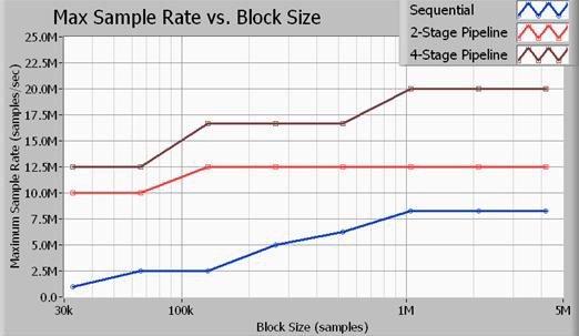
Figure 11. The throughput of multiloop structures is much faster than single-loop structures.
Figure 11 illustrates the maximum throughput in terms of sample rate, according to the acquisition size in samples. All benchmarks illustrated here were performed on 16-bit samples. In addition, the signal processing algorithm used was a seventh-order Butterworth low-pass filter with a cutoff of 0.45x sample rate. As the data illustrates, you achieve the most data throughput with the four-stage pipelined (multiloop) approach. Note that a two-stage signal processing approach yields better performance than the single-loop method (sequential), but it does not use the processor as efficiently as the four-stage method. The sample rates listed above are the maximum sample rates of both input and output for an NI PXIe-5122 high-speed digitizer and an NI PXIe-6537 high-speed digital I/O module. Note that at 20 MS/s, the application bus is transferring data at rates of 40 MB/s for input and 40 MB/s for output for a total bus bandwidth of 80 MB/s.
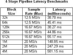
It is also important to consider that the pipelined processing approach does introduce latency between input and output. The latency is dependent upon several factors, including the block size and sample rate. Tables 1 and 2 below compare the measured latency according to block size and maximum sample rate for the single-loop and four-stage multiloop architectures.
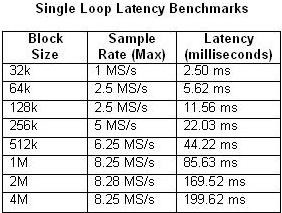
Tables 1 and 2. These tables illustrate the latency of single-loop and four-stage pipeline benchmarks.
As you expect, the latency increases as the CPU usage approaches 100 percent utilization. This is particularly evident in the four-stage pipeline example with a sample rate of 20 MS/s. By contrast, the CPU usage barely exceeds 50 percent in any of the single-loop examples.
Conclusion
PC-based instrumentation such as PXI and PXI Express modular instruments benefit greatly from advances in multicore processor technology and improved data bus speeds. As new CPUs improve performance by adding multiple processing cores, parallel or pipelined processing structures are necessary to maximize CPU efficiency. Fortunately, LabVIEW solves this programming challenge by dynamically assigning processing tasks to individual processing cores. As illustrated, you can achieve significant performance improvements by structuring LabVIEW algorithms to take advantage of parallel processing.

