Using the NI Digital I/O High-Reliability Feature Set for Industrial Applications
Overview
Contents
- Isolation – Protects Hardware and Permits Direct Connection to Industrial Sensors and Actuators
- Change Detection – Triggers Your Application after a Digital Event with Minimal Processor Usage
- Programmable Input Filters – Eliminate Glitches/Spikes and Remove Noise
- Programmable Power-Up States – Ensure Safe Operation When Connected to Pumps, Valves, Motors, and Relays
- Digital I/O Watchdogs – Detect Computer or Application Errors and Ensure Safe Recovery
- Summary
Isolation – Protects Hardware and Permits Direct Connection to Industrial Sensors and Actuators
Isolation physically and electrically separates two parts of a circuit and provides several advantages. It breaks ground loops, improves common-mode voltage and noise rejection, and it permits two parts of the circuit to be at different voltage levels. Isolation also protects computer circuitry. Industrial applications often require isolation to protect the electronics from transient voltage spikes and to provide greater common-mode noise rejection in electrically noisy environments containing machinery and inductive loads. In the case of channel-to-channel isolated I/O, each channel has its own ground terminal. In bank-isolated devices, each bank (or group) consists of several channels that share the same ground but are isolated from other banks.
Chemical Pigment Mixer
Chemical pigment mixing is a process that mixes inorganic chemicals for pigments and dyes. A chemical flow pump and a hydraulic control valve regulate the rate of flow for the two chemicals that are used. The pump and valve each have their own ground reference, and the pump is connected to an emergency stop switch that has the same ground reference. Furthermore, the two ground references differ by 5 V.
In the absence of isolation (see Figure 1), all three devices must be directly connected to one another, resulting a ground loop caused by the voltage difference in the ground references.
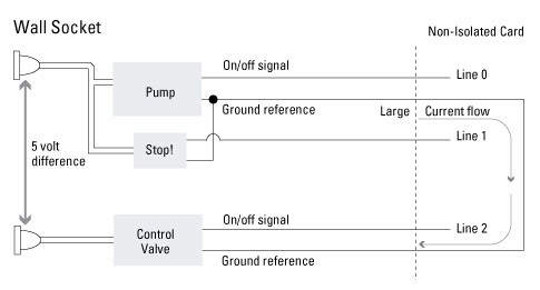
Figure 1. Nonisolated Connection
This flow of current can cause damage to pump and valve circuitry. In addition, incorrect readings can occur because of the increased load on the signal outputs of the devices. With a bank-isolated digital product (Figure 2), the devices can operate with their own ground reference, even with the large difference in voltage.
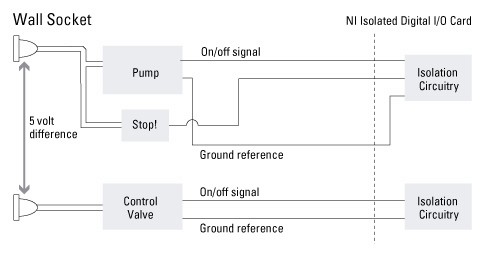
Figure 2. Bank-Isolated Connection
Industrial environments such as this one tend to be very noisy electrically. Some examples of noise sources are power cables, electric motors, and relays. In this noisy environment, isolation protects the digital circuitry of the I/O device from voltages that are beyond its normal operating range.
Change Detection – Triggers Your Application after a Digital Event with Minimal Processor Usage
In the event of a failure in a large automated system, it is imperative to be able to look back in time at the state of the system at the time of the failure. Equally important are the states leading up to the time of failure.
Power Plant Monitoring
In August 2003, several northeastern American cities were hit by an electrical blackout that left millions of people without power. During the investigation that followed, officials tried to determine the cause of the blackout. In an event such as this, the ability to view the state of the system prior to the blackout – minutes, hours, or even days before – is extremely valuable.
Because a system can change sporadically, it needs to be monitored at all times. On the other hand, constantly measuring the system at a set interval can result in enormous amounts of data, much of which is repetitive and irrelevant. Change detection provides the best of both worlds by removing the repetitive data while still recording important system events. Using change detection, data is captured only when a rising or falling edge is detected on specified inputs. For example, any time a relay opens or closes, the states of all relays will be captured and saved in case they are needed at a later time.
Creating a program to use change detection is simple in NI-DAQmx. The NI-DAQmx Timing VI has a new polymorphic instance that treats change detection just like any other buffered NI-DAQmx input operation (Figure 3). The programmer has complete control over which lines are used to detect a change. The rising-edge lines and falling-edge Lines control can be populated with any combination of input lines that physically exist on the device. The next section discusses how change detection is even more useful when used with digital input filtering.
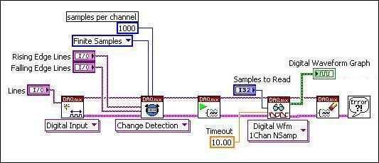
Figure 3. Configuring Change Detection in NI-DAQmx
Programmable Input Filters – Eliminate Glitches/Spikes and Remove Noise
As discussed previously, industrial environments can be electrically noisy. This noise can cause a variety of problems, one of which is unwanted readings. Any digital input device uses one or two voltage thresholds to determine if the input is high or low. When the input voltage is above the high threshold, the device reads a logical high. Conversely, if the voltage is below the low threshold, the device reads a logical low. If noise is present, the input voltage could cross the thresholds unexpectedly, causing an incorrect high or low reading. In other cases, a signal may appear to change state several times, when in reality it changed only once.
Oil Refinery
In oil refineries, a key switch may be used to activate the flow of crude oil into a chamber for refining. The switch, however, tends to exhibit a lot of bouncing. Much like a ball bouncing on a hard surface, one of the metal contacts will tend to bounce when it is forced into the other contact. The repeated toggling of the signal would cause the pump it is controlling to rapidly switch on and off, which can accelerate wear on the pump and eventually lead to a premature failure. In addition, if you were using an NI device with change detection to acquire this signal, the input buffer would fill up unnecessarily.
If input filters are enabled on the NI device, it will eliminate the erroneous readings caused by the bouncing switch. It does this by ignoring any pulses that are too small in width. The NI device can then output the filtered signal to the pump. With programmable input filters, the user can programmatically select the minimum pulse width that is guaranteed to pass (Figure 4).
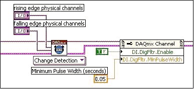
Figure 4. Configuring Input Filters in NI-DAQmx
Any pulse that is greater than the specified minimum pulse is guaranteed to pass, and any pulse that is less than half of the specified pulse width is guaranteed to be filtered. Pulses that fall between half of the pulse width and one entire pulse width may or may not pass.
Programmable Power-Up States – Ensure Safe Operation When Connected to Pumps, Valves, Motors, and Relays
When a computer is powered on, various components begin their own power-up routines to ensure that they reach a functional and expected state. If a digital output device is used inside the computer to control machinery or an industrial process, it is important that the digital outputs are also initialized to a known state. Changing the outputs typically requires that an application is running, but the device may be on for several minutes before the application can start. It is important that there be a way for the digital device itself to set its outputs as soon as it receives power.
Rolling Mill
In a rolling mill, heated steel is forced through rolling machinery to create steel beams of varying widths. The rolling motor is controlled by a digital output line from a digital I/O device. When the computer is powered on, the rolling motors must be turned off to prevent any steel from being wasted during start-up. If the digital I/O device does not provide a way to guarantee the initial outputs, the computer must completely boot and a control program must be started before known states are output on the channels. This lack of control could result in the waste of expensive raw materials and equipment damage. Glitch-free power-up states ensure that all digital outputs will begin in a known state any time the device is powered on. Because none of the machinery turns on unexpectedly, no steel is wasted.
On the new NI digital products, programmable power-up states are implemented in an EEPROM on the device. The power-up states in the EEPROM can be changed programmatically by either of two different methods. A) The NI-DAQmx Set Power-Up States VI can be run in LabVIEW (Figure 5). When the VI is run, the settings are downloaded to the EEPROM.
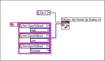
Figure 5. Power-Up States in LabVIEW
B) These settings can also be written from NI Measurement & Automation Explorer (MAX) by opening the properties page for the device. The desired settings are written when the user clicks the OK button (Figure 6). Both of these methods are easy to use for implementing programmable power-up states.
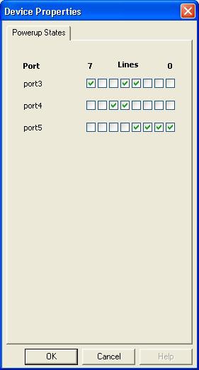
Figure 6. Power-Up States in MAX
Digital I/O Watchdogs – Detect Computer or Application Errors and Ensure Safe Recovery
Control systems typically require redundancy or fail-safe mechanisms of some kind. In the event of the unexpected failure of some component of the system, the fail-safe mechanism will take over and place the system into a known safe state. The digital I/O watchdogs on the new NI industrial digital products provide a method for detecting system errors and recovering from them safely. Note that the NI-DAQmx Watchdog feature is meant to protect a system from software errors and hangs. In the case of a PXI system with remote control via MXI, a lost MXI connection could result in unexpected Watchdog behavior and therefore improperly implemented Watchdog states.
Candy Factory
Bubble gum is cut and packaged at a candy factory. A blade slices the gum into pieces, and a conveyer moves the pieces into a packaging machine. Both the blade and the conveyer are controller by digital output lines. If the control application hangs, the conveyer would ideally stop moving and the blade would be moved away from the gum. Otherwise, machinery could be damaged, and gum could be needlessly wasted. Digital I/O watchdogs provide a way to set the outputs of a digital device to known safe states in the event of a system fault or failure. The digital device constantly receives confirmation that the computer is still functioning properly. If this confirmation is not received within a programmable timeout, the safe states are written to the outputs. Figure 7 below shows the flow of information during normal operation.
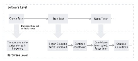
Figure 7. Watchdog Timer Flowchart Showing Separate Hardware and Software Levels
Once the watchdog is configured and started, the software application must continuously reset the timer to avoid expiration. This task is done with the NI-DAQmx Control Watchdog Task VI as shown in Figure 8. This reset serves as the confirmation discussed above.
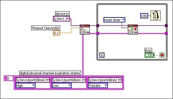
Figure 8. Configuring and Resetting Watchdog Timer
In the continued flow chart in Figure 9, if a fault occurs (such as the computer hanging), the hardware will continue to count down until the timeout expires. At this time, the predefined safe states are written to the outputs, and all future writes are ignored.
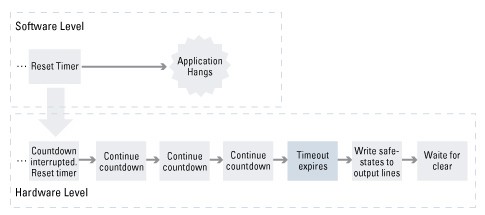
Figure 9. Flowchart Showing Watchdog Timer Expiration
In order for the device to become responsive to hardware commands again, the expiration must be cleared, again using the NI-DAQmx Control Watchdog Task VI as in Figure 10.
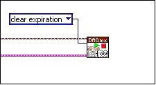
Figure 10. Clearing the Expiration
Digital I/O watchdogs protect against various types of failures, including application hangs, computer hangs, and overall system crashes. Important to note from the above description is that once configured, the watchdog does not rely on software to output the safe states. Software is required only to reset the timer.
Summary
The new high-reliability industrial feature set is a powerful way to regulate industrial processes, reduce noise, limit machine damage, and prevent waste. All of the programmable features are easily implemented with NI-DAQmx, so they can quickly be deployed to the factory floor. The isolated products provide a way for high-voltage digital signals to be acquired and generated, protecting the internal circuitry of both the I/O device and the computer. With this comprehensive set of features, you can create a robust, professional industrial system.