NI Vision Image Acquisition System Concepts
Overview
Setting up your imaging environment is a critical first step to any imaging application. If you set up your system properly, you can focus your development energy on the application rather than problems from the environment, and you can save precious processing time at run time. Consider the following three elements when setting up your system: imaging system parameters, lighting, and motion.
Contents
Fundamental Parameters of an Imaging System
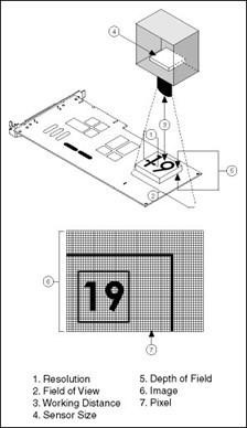
Before you acquire images, you must set up your imaging system. Five fundamental parameters comprise an imaging system: resolution, field of view, working distance, sensor size, and depth of field. Figure 1 illustrates these concepts.
Figure 1. Fundamental Parameters of an Imaging System
- Resolution: the smallest feature size on your object that the imaging system can distinguish
- Field of view: the area of inspection that the camera can acquire
- Working distance: the distance from the front of the camera lens to the object under inspection
- Sensor size: the size of a sensor's active area
- Depth of field: the maximum object depth that remains in focus
The way you set up your system depends on the type of analysis, processing, and inspection you need to do. Your imaging system should produce images with high enough quality to extract the information you need from the images. Five factors contribute to overall image quality: resolution, contrast, depth of field, perspective, and distortion.
Resolution
Resolution indicates the amount of object detail that the imaging system can reproduce. You can determine the required resolution of your imaging system by measuring in real-world units the size of the smallest feature you need to detect in the image.
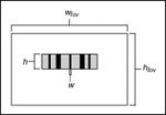
Figure 2 depicts a barcode. To read a barcode, you need to detect the narrowest bar in the image. The resolution of your imaging system in this case is equal to the width of the narrowest bar (w).
Figure 2. Determining the Resolution of Your Imaging System
To make accurate measurements, a minimum of two pixels should represent the smallest feature you want to detect in the digitized image. In Figure 2, the narrowest vertical bar (w) should be at least two pixels wide in the image. With this information you can use the following guidelines to select the appropriate camera and lens for your application.
- Determine the sensor resolution of your camera.
Sensor resolution is the number of columns and rows of CCD pixels in the camera sensor. To compute the sensor resolution, you need to know the field of view (FOV). The FOV is the area under inspection that the camera can acquire. The horizontal and vertical dimensions of the inspection area determine the FOV. Make sure the FOV encloses the object you want to inspect.
Once you know the FOV, you can use the following equation to determine your required sensor resolution:
sensor resolution = (FOV/resolution) x 2
= (FOV/size of smallest feature) x 2
Use the same units for FOV and size of smallest feature. Choose the FOV value (horizontal or vertical) that corresponds to the orientation of the smallest feature. For example, you would use the horizontal FOV value to calculate the sensor resolution for Figure 2.
Cameras are manufactured with a limited number of standard sensor resolutions. The table below shows some typical camera sensors available and their approximate costs.
Table 1.
| Number of CCD Pixel
| Cost | FOV | Resolution |
|---|---|---|---|
640 x 480 | $500+ | 60 mm | 0.185 mm |
768 x 572 | $750+ | 60 mm | 0.156 mm |
1280 x 1024 | $5000+ | 60 mm | 0.093 mm |
2048 x 2048 | $22,000+ | 60 mm | 0.058 mm |
3072 x 2048 | $32,000+ | 60 mm | 0.039 mm |
If your required sensor resolution does not correspond to a standard sensor resolution, choose a camera whose sensor resolution is larger than you require or use multiple cameras. Be aware of camera prices as sensor sizes increase.
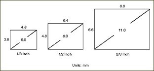
By determining the sensor resolution you need, you narrow down the number of camera options that meet your application needs. Another important factor that affects your camera choice is the physical size of the sensor, known as the sensor size. Figure 3 shows the sensor size dimensions for standard 1/3 Inch, 1/2 Inch, and 2/3 Inch sensors. Notice that the names of the sensors do not reflect the actual sensor dimensions.
Figure 3. Common Sensor Sizes and Their Actual Dimensions
In most cases, the sensor size is fixed for a given sensor resolution. If you find cameras with the same resolution but different sensor sizes, you can determine the sensor size you need based on the next guideline.
- Determine the focal length of your lens.
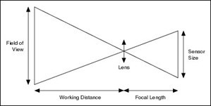
A lens is primarily defined by its focal length. Figure 4 illustrates the relationship between the focal length of the lens, field of view, sensor size, and working distance.
Figure 4. Relationship Between Focal Length, FOV, Sensor Size, and Working Distance
The working distance is the distance from the front of the lens to the object under inspection.
If you know the FOV, sensor size, and working distance, you can compute the focal length of the lens you need using the following formula:
focal length = sensor size x working distance / FOV
Lenses are manufactured with a limited number of standard focal lengths. Common lens focal lengths include 6 mm, 8 mm, 12.5 mm, 25 mm, and 50 mm. Once you choose a lens whose focal length is closest to the focal length required by your imaging system, you need to adjust the working distance to get object under inspection in focus.
Lenses with short focal lengths (less than 12 mm) produce images with a significant amount of distortion. If your application is sensitive to image distortion, try to increase the working distance and use a lens with a higher focal length. If you cannot change the working distance, you are somewhat limited in choosing your lens.
Note: As you are setting up your system, you need to fine tune the various parameters of the focal length equation until you achieve the right combination of components that match your inspection needs and meet your cost requirements.
Contrast
Resolution and contrast are closely related factors contributing to image quality. Contrast defines the differences in intensity values between the object under inspection and the background. Your imaging system should have enough contrast to distinguish objects from the background. Proper lighting techniques can enhance the contrast of your system.
Depth of Field
The depth of field of a lens is its ability to keep in focus objects of varying heights or objects located at various distances from the camera. If you need to inspect objects with various heights, choose a lens that can maintain the image quality you need as the objects move closer to and further from the lens. You can increase the depth of field by closing the iris of the lens and providing more powerful lighting.
Telecentric lenses work with a wide depth of field. With a telecentric lens, you can image objects of different distances from the lens and the objects stay in focus.
Perspective
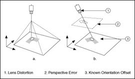
Perspective errors occur when the camera axis is not perpendicular to the object under inspection. Figure 5a shows an ideal camera position. Figure 5 shows a camera imaging an object from an angle.
Figure 5. Camera Angle Relative to the Object Under Inspection
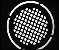
Figure 6a shows a grid of dots. Figure 6 illustrates perspective errors caused by a camera imaging the grid from an angle.
Figure 6. Perspective and Distortion Errors
Try to position your camera perpendicular to the object under inspection to reduce perspective errors. Integration constraints may prevent you from mounting the camera perpendicular to the scene. Under these constraints, you can still take precise measurements by correcting the perspective errors with spatial calibration techniques.
Distortion
Nonlinear distortion is a geometric aberration caused by optical errors in the camera lens. A typical camera lens introduces radial distortion. This causes points that are away from the lens's optical center to appear further away from the center than they really are. Figure 4c illustrates the effect of distortion on a grid of dots. When distortion occurs, information in the image is misplaced relative to the center of the field of view, but the information is not necessarily lost. Therefore, you can undistort your image through spatial calibration.
Lighting
One of the most important aspects of setting up your imaging environment is proper illumination. Images acquired under proper lighting conditions make your image processing software development easier and overall processing time faster. One objective of lighting is to separate the feature or part you want to inspect from the surrounding background by as many gray levels as possible. Another goal is to control the light in the scene. Set up your lighting devices so that changes in ambient illumination-such as sunlight changing with the weather or time of day-do not compromise image analysis and processing.
Common types of light sources include halogen, LED, fluorescent, and laser. To learn more about light sources, review NI’s Practical Guide to Machine Vision Lighting.
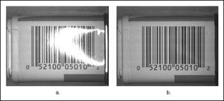
The type of lighting technique you select can determine the success or failure of your application. Improper lighting can cause shadows and glares that degrade the performance of your image processing routine. For example, some objects reflect large amounts of light because of their curvature or surface texture. Highly directional light sources increase the sensitivity of specular highlights (glints), as shown on the barcode in Figure 7a. Figure 7b shows an image of the same barcode acquired under diffused lighting.
Figure 7. Using Diffused Lighting to Eliminate Glare
Backlighting is another lighting technique that can help improve the performance of your vision system. If you can solve your application by looking at only the shape of the object, you may want to create a silhouette of the object by placing the light source behind the object you are imaging. By lighting the object from behind, you create sharp contrasts which make finding edges and measuring distances fast and easy. Figure 8 shows a stamped metal part acquired in a setup using backlighting.
Figure 8. Using Backlighting to Create a Silhouette of an Object
Many other factors, such as the camera you choose, contribute to your decision about the appropriate lighting for your application. For example, you may want to choose lighting sources and filters whose wavelengths match the sensitivity of the CCD sensor in your camera and the color of the object under inspection. Also, you may need to use special lighting filters or lenses to acquire images that meet your inspection needs.
Movement Considerations
In some machine vision applications, the object under inspection moves or has moving parts. In other applications, you may need to incorporate motion control to position the camera at various places around the object or move the object under the camera. Images acquired in applications that involve movement may appear blurry. Follow the suggestions below to reduce or eliminate blur caused by movement.
One way to eliminate blur resulting from movement is to use a progressive scan camera. A global (progressive scan) shutter exposes the entire frame of pixels of a camera sensor at the same time. This method is necessary for imaging moving objects, since it allows you to acquire an image without blurring when a moving object is involved. A rolling shutter exposes rows of pixels line by line sequentially. This method can cause bad effects, such as skewing, when imaging moving objects. While rolling shutter cameras can be used for some stationary inspection applications, global shutter cameras are required for inspections of moving objects. NI IMAQdx driver can interface cameras of these different types from different various communication bus (USB 3.0 Vision, GigE Vision, Camera Link).
Another method for eliminating movement-induced blur in images is to use a strobe light with a progressive scan camera. Camera sensors acquiring images of a moving object require a short exposure time to avoid blur. To obtain an image with enough contrast, the sensor needs to be exposed to enough light during a short amount of time. Strobe lights emit light for only microseconds at a time, thus limiting the exposure time of the image to the CCD and resulting in a very crisp image. Strobe lights require synchronization with the camera. NI IMAQdx Driver can interface and communicate with the camera hardware to configure triggers and strobe the lights.
Another way to avoid blur resulting from moving objects is to use a line scan camera. A line scan camera acquires a single line of the image at a time, eliminating the blur.
