From Saturday, Nov 23rd 7:00 PM CST - Sunday, Nov 24th 7:45 AM CST, ni.com will undergo system upgrades that may result in temporary service interruption.
We appreciate your patience as we improve our online experience.
From Saturday, Nov 23rd 7:00 PM CST - Sunday, Nov 24th 7:45 AM CST, ni.com will undergo system upgrades that may result in temporary service interruption.
We appreciate your patience as we improve our online experience.
National Instruments offers switches with scanning capabilities. This document explains the different scanning options, hardware setup, and programming techniques for scanning several modules. Readers should have a basic knowledge of single module scanning hardware setup and programming. Single module information can be found in the NI Switch Help under Programming with NI-SWITCH»Features»Scanning»Scanning NI Switches with NI DMM.
Scanning is typically used when the timing of connections needs to be synchronized with an event of another device such as a measurement device. Scanning consists of setting up a list of connections to be made upon an event. The connections are entered in a scan list that is downloaded to the memory of the switch. The first entry in the scan list is executed when the switch module is armed and the triggering settings will determine how it advances through the list. The scan list can be executed continuously or a finite number of times.
There are two hardware-timed scanning options; Synchronous Scanning, and Handshaking.
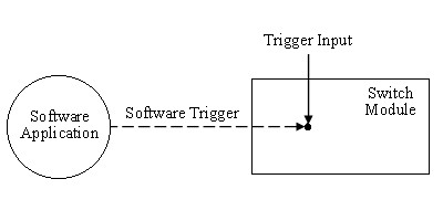
Software Trigger Scanning
In software trigger scanning, the scan list advances when niSwitch Send Software Trigger.vi (niSwitch_SendSoftwareTrigger) is called. Each subsequent entry is executed after each additional call of niSwitch Send Software Trigger.vi (niSwitch_SendSoftwareTrigger).
Synchronous Scanning
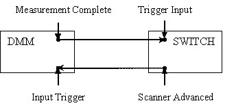
Each entry in the scan list is executed when the switch receives a digital pulse. This digital pulse is the Trigger Input (TI). A common use of synchronous scanning is with a digital multimeter (DMM). The DMM is programmed to take measurements at regular intervals and generates a digital pulse; Measurement Complete (MC). When the switch receives this digital pulse, it advances to the next entry in its scan list. You must program the DMM interval time between measurements to, at least, the time needed for the switch to activate and settle.

Handshaking
Handshaking is very similar to synchronous scanning but the switch is now sending a digital pulse, called Scanner Advanced (SA), back to the measurement device after each set of connections. The DMM does not need to be programmed to take measurements at regular intervals but rather to accept a pulse as a trigger for its measurements. The DMM needs to be armed and ready to accept a trigger for its first measurement. The switch is then armed, executes its first entry in the scan list, generates the SA trigger and waits for a digital pulse to execute its next entry. When the DMM receives this digital pulse, it takes the first measurement and generates the MC. When the switch receives this digital pulse, it executes the next entry in the scan list, generates another SA and so on.
PXI switches do not need a controller since they are controlled, like any other PXI cards, by the PXI controller of the PXI chassis and can be triggered by measurement devices. SCXI switches require a dedicated controller like a NI 4021, NI 4060 or NI 407x and can also be triggered by measurement devices, generally DMMs.
In SCXI switch scanning, the switch controller is the liaison between the Application Development Environment (ADE) and the switch. Using SCXI protocol, the controller communicates with the switch to set it with the parameters selected in the program and to download the scan list to the switch memory. The device sending the triggers is responsible for advancing the switch scan list through its entries.
The switch controller and the triggering device do not have to be the same device. For example, the NI 4021 can only be used as a switch controller but does not have triggering capabilities. You need to use an NI DMM to trigger the SCXI switch when it is controlled by an NI 4021. If you are using an NI DMM for controlling SCXI switches, you can also send triggers without the need for another device. The controlling DMM used, the cabling scheme and the SCXI switches will dictate the scanning capabilities, i.e. synchronous scanning or handshaking.
Two cables are used to control or trigger SCXI switches: the SH9MD-AUX cable and the AUX trigger cable.
SH9MD-AUX Cable
This cable is used to carry SCXI communication from a switch controller (4021, DMM, E series) to an SCXI switch.
- When this cable is used with an NI 4060, it can only carry SCXI communication and the MC signal from the DMM to the switch which implies that only synchronous scanning is possible.
- When this cable is used with an NI 407x, it can carry SCXI communication, the MC signal and the SA from the switch to the DMM, synchronous scanning and handshaking are then possible.
- When this cable is used with an NI 4021, only SCXI communication is possible. Scanning triggers cannot be sent though this cable.
AUX Trigger Cable
This cable is used to separate triggers from an NI DMM. With this cable the DMM can send and receive triggers but cannot control SCXI switches. These two triggers connect to a switch module terminal block or front panel. One branch of this cable is labeled VOLTMETER COMPLETE which carries the MC signal from the DMM. The other branch is labeled EXT TRIG IN which carries the SA from the switch to the DMM. This cable can be used between a PCI or PXI DMM and a PXI or SCXI switch.

High Voltage SCXI Backplane
SCXI switches require a backplane adapter to connect the SH9MD-AUX cable. The backplane routes signals from the SH9MD-AUX cable to the back of the switch in the right-most position on the backplane. Theses backplanes can connect to two or eight SCXI switches.
The PXI-1011 has an integrated backplane which connects to all 8 SCXI switches but when creating a SCXI chassis in MAX, you will need to select one SCXI switch that will be receiving the signals from the SH9MD-AUX cable.
If you are using the SCXI-1127, SCXI- 1128 or SCXI-1129 you can use these backplanes to share high voltage signals among all the SCXI switches connected to the backplane and to route high voltage signals to the DMM. Unlike the digital signals from the SH9MD-AUX cable that is routed to only one SCXI switch, the high voltage signals are shared among all switches connected to the backplane. The cable HV8-BAN4 is used to connect SCXI backplanes to an NI DMM. The 9 Pin DIN connectors for the SH9MD-AUX cable are circled in the Figure 5. The three available backplane kits are: SCXI-1357, SCXI-1358, and or SCXI-1359. Log on to ni.com for information on these kits.

SCXI switches require a backplane to connect the SH9MD-AUX cable for controlling or triggering. In a multi-module scanning, only one SCXI switch needs to be connected to the controller or to the triggering device.
Several factors need to be considered when you are using NI switches in scanning operations: switch capabilities, chassis capabilities, and scanning mode. In a specific hardware setup, multi-module scanning will only be possible if single module scanning is possible. Single module scanning capabilities doesn’t necessary ensures that a multi-module scanning operation is possible.
|
INPUT
Trigger Input |
OUTPUT
Scanner Advanced | |
|
SCXI-1127
SCXI-1128 |
SCXI trig 0
Front, Rear |
SCXI trig 2
Front |
|
SCXI-1129
|
All SCXI trig
Front, Rear |
All SCXI trig
Front |
|
SCXI-1193
SCXI-1166 SCXI-1130 SCXI-1167 |
All SCXI trig
Front, Rear |
All SCXI trig
Front, Rear |
|
SCXI-1169
|
All SCXI trig
Rear |
All SCXI trig
Rear |
|
PXI-2501
PXI-2503 PXI-2593 PXI-2566 PXI-2529 PXI-2530 PXI-2567 |
All PXI trig
Front |
All PXI trig
Front |
|
PXI-2532
PXI-2565 PXI-2568 PXI-2569 PXI-2570 PXI-2575 PXI-2590 PXI-2591 |
All PXI trig
|
All PXI trig
|
We can categorize different DMM/switch systems according to the DMM, the switch and the cable used. In the table below, we assigned a letter for each possible system.
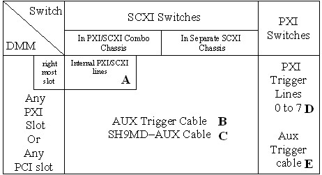
- System A: the DMM is controlling and triggering the SCXI switch using internal PXI/SCXI lines of a PXI/SCXI combo chassis. The DMM is placed on the right most PXI slot of a combo chassis.
- System B: the DMM is not controlling the SCXI switch but it is triggering it using the AUX trigger cable. The SCXI switch is controlled by another device.
- System C: the DMM is controlling and triggering the SCXI switch using the SH9MD-AUX cable.
- System D: the DMM is triggering the PXI switch using PXI trigger lines. PXI-4060 only uses PXI trigger lines 0 to 6. PXI-407x uses PXI trigger lines 0 to 7.
- System E: a PXI or PCI DMM is triggering the PXI switch using the AUX trigger cable
From Table 2, we can now setup a table showing scanning capabilities for every National Instruments switches.
|
Systems
Switches |
A
PXI/SCXI internal lines |
B
AUX trigger cable |
C
SH9MD AUX cable |
D
PXI trigger lines |
E
AUX trigger cable |
| 1127, 1128 | S7 | S6,H9 | S5 | ||
| 1129 | S7,H*10 | S6,H9 | S5 | ||
| 1193, 1166 1130, 1167 1169 | S7,H*10 | S6,H9 | S5,H*8 | ||
| 2501, 2503 2566, 2593 2530, 2567 2529 | S1,H3 | S2,H4 | |||
| 2565, 2590 2591, 2569 2570, 2568 2532, 2575 | S1,H3 | ||||
| 1160, 1161 1163R, 1190 1191, 1192 | Do not support scanning |
The number next to S and H indicates the setup number. The different setups are discussed in the Multi-module Scanning section. For example if you would like to do synchronous scanning with multiple SCXI-1130 using an AUX trigger cable refer to setup 6. If you would like to do handshaking with multiple PXI-2529 using PXI trigger lines refer to setup 3.
NI-DAQmx API
To write a program to scan multiple switches using the NI-DAQmx API, use shipping NI-DAQmx examples for switches: Switch Scanning with DMM - synchronous.vi for synchronous scanning setups and Switch Scanning with DMM - Handshaking.vi for handshaking setups. Add DAQmx Switch Set Topology and Reset.vi (Figure 6) for all the switches in the scanning operation. The NI-DAQmx shipping examples for switches are installed in \Program Files\National Instruments\LabVIEW\7.0\examples\DAQmx\Switches.
In NI-DAQmx Trigger Input (TI) is called Advance Trigger and Scanner Advanced (SA) is called Advance Complete Trigger.

NI-SWITCH API
To write a program to scan multiple switches using the NI-SWITCH API, use shipping NI-SWITCH examples: niSwitch DMM Switch Synchronous Scanning.vi for synchronous scanning setups and niSwitch DMM Switch Handshaking for handshaking setups. Duplicate the switches LabVIEW VIs for all the switches involved in the scanning operation. The NI-SWITCH shipping examples are installed in \Program Files\National Instruments\LabVIEW 7.0\examples\instr\niSwitch.
Scan List for Multiple Switches Under NI-SWITCH API
Use the following process for filling out the scan lists of the switches in the scanning operation. In the example we will scan four consecutive channels of three switches.
Scan List for Switch #1
In the scan list of switch #1, enter the channels that you want to scan followed by the number of semicolons “;” equal to the sum of the channels in the other scan lists plus one. For the purpose of our example, the total number of semicolons after the channel entry will be nine.
The scan list will look like this: ch0:3com0;;;;;;;;;
1. Channels of switch #1 to be scanned followed by one semicolon. This entry is the same as for scanning a single module.
2. Number of semicolons equal to the number of channels of switch #2 instructs switch #1 not to react to the triggers dedicated to switch #2. These semicolons are dummy entries corresponding to the channels of the switch #2.
3. Number of semicolons equal to the number of channels of switch #3 instructs switch #1 not to react to the triggers dedicated to switch #3. These semicolons are dummy entries corresponding to the channels of switch #3
Scan List for Switch #2
In the scan list of switch #2, enter the number of semicolons equal to the channels in the first scan list, then the channels that you want to scan in switch #2 and the number of semicolons equal to the sum of channels in the remaining scan lists plus one. For the purpose of our example, the number of semicolons before the channel entry will be four, the number of semicolons after the channel entry will be five.
The scan list will look like this: ;;;;ch0:3com0;;;;;
1. Number of semicolons equal to the number of channels of switch #1 instructs switch #2 not to react to the triggers dedicated to switch #1.These semicolons are dummy entries corresponding to the channels of the switch #1.
2. Channels of switch #2 to be scanned followed by one semicolon. This entry is the same as for scanning a single module.
3. Number of semicolons equal to the number of channels switch #3 instructs switch #2 not to react to the triggers dedicated to switch #3. These semicolons are dummy entries corresponding to the channels of switch #3.
Scan List for Switch #3
In the scan list of switch #3, enter the number of semicolons equal to sum of the channels in all the previous scan lists, then the channels that you want to scan followed by one semicolon. For the purpose of our example, the number of semicolons before the channel entry will be 8.
The scan list will look like this: ;;;;;;;;ch0:3com0;
1. Number of semicolons equal to the number of channels of switch #1 instructs switch #3 not to react to the triggers dedicated to switch #1. These semicolons are dummy entries corresponding to the channels of the switch #1.
2. Number of semicolons equal to the number of channels of switch #2 instructs switch #3 not to react to the triggers dedicated to switch #2. These semicolons are dummy entries corresponding to the channels of switch #2.
3. Channels of switch #3 to be scanned followed by one semicolon. This entry is the same as for scanning a single module.
Table 4 provides information on supported API for all National Instruments switches with scanning capabilities.
|
PXI Switches
|
NI-DAQ
|
NI-SWITCH
| |||||
|
mx 7.1
|
mx 7.2
|
mx 7.3
|
2.0
|
2.1
|
2.2
|
2.3
| |
|
PXI-2501
|
-
|
Ö
|
Ö
|
Ö
|
Ö
|
Ö
|
Ö
|
|
PXI-2503
|
-
|
Ö
|
Ö
|
Ö
|
Ö
|
Ö
|
Ö
|
|
PXI-2529
|
Ö
|
Ö
|
Ö
|
-
|
Ö
|
Ö
|
Ö
|
|
PXI-2530
|
Ö
|
Ö
|
Ö
|
-
|
Ö
|
Ö
|
Ö
|
|
PXI-2565
|
-
|
Ö
|
Ö
|
Ö
|
Ö
|
Ö
|
Ö
|
|
PXI-2566
|
Ö
|
Ö
|
Ö
|
Ö
|
Ö
|
Ö
|
Ö
|
|
PXI-2567
|
Ö
|
Ö
|
Ö
|
-
|
Ö
|
Ö
|
Ö
|
|
PXI-2590
|
-
|
Ö
|
Ö
|
Ö
|
Ö
|
Ö
|
Ö
|
|
PXI-2591
|
-
|
Ö
|
Ö
|
Ö
|
Ö
|
Ö
|
Ö
|
|
PXI-2593
|
Ö
|
Ö
|
Ö
|
Ö
|
Ö
|
Ö
|
Ö
|
|
PXI-2568
|
-
|
Ö
|
Ö
|
-
|
-
|
Ö
|
Ö
|
|
PXI-2569
|
-
|
Ö
|
Ö
|
-
|
-
|
Ö
|
Ö
|
|
PXI-2570
|
-
|
Ö
|
Ö
|
-
|
-
|
Ö
|
Ö
|
|
PXI-2532
|
-
|
-
|
Ö
|
-
|
-
|
-
|
Ö
|
|
PXI-2575
|
-
|
-
|
Ö
|
-
|
-
|
-
|
Ö
|
|
SCXI Switches
|
NI-DAQ
|
NI-SWITCH
| |||||
|
mx 7.1
|
mx 7.2
|
mx 7.3
|
2.0
|
2.1
|
2.2
|
2.3
| |
|
SCXI-1127
|
Ö
|
Ö
|
Ö
|
Ö
|
Ö
|
Ö
|
Ö
|
|
SCXI-1128
|
Ö
|
Ö
|
Ö
|
Ö
|
Ö
|
Ö
|
Ö
|
|
SCXI-1129
|
Ö
|
Ö
|
Ö
|
Ö
|
Ö
|
Ö
|
Ö
|
|
SCXI-1130
|
Ö
|
Ö
|
Ö
|
-
|
Ö
|
Ö
|
Ö
|
|
SCXI-1160
|
Ö
|
Ö
|
Ö
|
Ö
|
Ö
|
Ö
|
Ö
|
|
SCXI-1161
|
Ö
|
Ö
|
Ö
|
Ö
|
Ö
|
Ö
|
Ö
|
|
SCXI-1163R
|
Ö
|
Ö
|
Ö
|
Ö
|
Ö
|
Ö
|
Ö
|
|
SCXI-1166
|
Ö
|
Ö
|
Ö
|
Ö
|
Ö
|
Ö
|
Ö
|
|
SCXI-1167
|
Ö
|
Ö
|
Ö
|
-
|
Ö
|
Ö
|
Ö
|
|
SCXI-1193
|
Ö
|
Ö
|
Ö
|
Ö
|
Ö
|
Ö
|
Ö
|
|
SCXI-1169
|
-
|
Ö
|
Ö
|
-
|
-
|
Ö
|
Ö
|
Synchronous
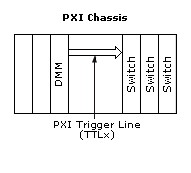
All PXI switches can receive an input trigger from PXI trigger lines. In this setup there are no cables needed from the DMM to the PXI switches for triggering. The DMM will send its MC to the PXI switches through a PXI trigger line.
Programming PXI Switches Using NI-DAQmx
Use DAQmx Multi Switch Sync.vi
Refer to Table 4 for switches that can be programmed under NI-DAQmx. Enter in the scan list, all the channels for each module to be scanned using the NI-DAQmx scan list syntax /Switch/channel1->channel2.
For the Advance Trigger Source input, select any PXI trigger lines from any module. In our example, we selected “/PXI1Slot4/PXI_Trig0”. The DMM MC destination should be set to the same trigger line “TTL 0”.

Programming PXI Switches Using NI-SWITCH
Use niSwitch Multi Switch Synch Int.vi
Enter channels in the scan lists according to the process described in the Scan List for Multiple Switches under NI-SWITCH API section.
The trigger input should be the same for all switches and coincide with the destination of the MC signal from the DMM.

Some PXI switches can receive an input trigger from the front panel or terminal block. In this setup you will use an AUX trigger cable. Connect the MC signal from the DMM to the appropriate external trigger input terminal on the front panel or in the terminal block of one PXI switch.
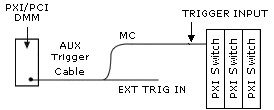
Programming PXI Switches Using NI-DAQmx
Use DAQmx Multi Switch Sync.vi
Refer to Table 4 for switches that can be programmed under NI-DAQmx. Enter in the scan list, all the channels for each module to be scanned using NI-DAQmx scan list syntax /Switch/channel1->channel2.
For the Advance Trigger Source input, select “/PXI1Slot4/TrigIn” if the AUX trigger cable from the DMM is connected to the front panel or terminal block of the PXI switch in Slot 4. The NI DMM MC destination should be set to “External”.

Programming PXI Switches Using NI-SWITCH
Use niSwitch Multi Switch Sync Ext.vi
Enter channels in the scan lists according to the process described in the Scan List for Multiple Switches under NI-SWITCH API section.
Add niSwitch Route Trigger Input.vi to the configuration of switch where the AUX trigger cable from the DMM is connected. Select “front connector” for trigger input connector and “TTLn” for trigger input bus line. This PXI trigger line should also be selected in Trigger Input for all switches. The DMM MC destination should set to “external”.
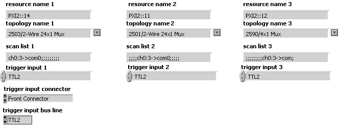
Handshaking
To handshake with multiple PXI switches you can use internal PXI trigger lines. In this setup, a trigger cable is not needed between the DMM and the PXI switches.
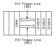
Programming PXI Switches Using NI-DAQmx
Use DAQmx Multi Switch Hand.vi
Refer to Table 4 for switches that can be programmed under NI-DAQmx. Enter in the scan list, all the channels for each module to be scanned using the NI-DAQmx scan list syntax /Switch/channel1->channel2.
For the Advance Trigger Source input, select any PXI trigger line from any PXI switch and for Advance Complete Output terminal select another PXI trigger line. In our example, we selected “PXI1Slot4/PXI_Trig0” and “PXI1Slot4/PXI_Trig1”. The DMM MC destination should be set to the same PXI trigger line as the Advance Trigger Source and the Trigger Input should be set to the same PXI trigger line than the Advance Complete Output terminal.
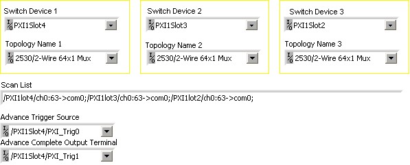
Programming PXI Switches Using NI-SWITCH
Use niSwitch Multi Switch Hand Int.vi
Enter channels in the scan lists according to the process described in the Scan List for Multiple Switches under NI-SWITCH API section.
The trigger input should be the same PXI trigger line for all switches and should coincide with the destination of the DMM MC signal. The scan advanced output should be the same PXI trigger line for all switches and coincide with the trigger source of the DMM.

Some PXI switches can receive their input trigger and send their scan advanced from and to the front panel or terminal block. In this setup you will use an AUX trigger cable. Connect the MC signal from the DMM to the external trigger input terminal on the front panel or in the terminal block of one PXI switch. Also connect the Ext Trig In signal of the DMM to the Scanner Advanced terminal on the front panel or in the terminal block of the same PXI switch.
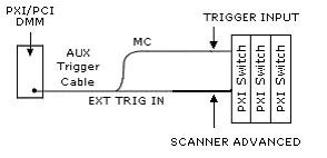
Programming PXI Switches Using NI-DAQmx
Use DAQmx Multi Switch Hand.vi
Refer to Table 4 for switches that can be programmed under NI-DAQmx. Enter in the scan list, all the channels for each module to be scanned using the NI-DAQmx scan list syntax /Switch/channel1->channel2.
Select “/PXI1Slot4/TrigIn” and “/PXI1Slot4/TrigOut” for the Advance Trigger Source and for the advance Complete Output Terminal respectively if the AUX trigger cable from the DMM is connected to the font panel or the terminal block of the PXI switch in Slot 4. The DMM MC destination and the Trigger Source should be set to “External”.
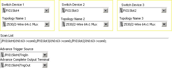
Programming PXI Switches Using NI-SWITCH
Use niSwitch Multi Switch Hand Ext.vi
Enter channels in the scan lists according to the process described in the Scan List for Multiple Switches under NI-SWITCH API section.
Add niSwitch Route Trigger input.vi and niSwitch Route Scan Advanced Output.vi before the niSwitch commit.vi of the switch where the AUX trigger cable from the DMM is connected. Select “Front Connector” for Trigger input connector, and for Scan Advanced output connector. Select a PXI trigger line for Trigger input bus line, and a different PXI trigger line for Scan Advanced Output Bus Line. Select the same PXI trigger line for Trigger Input Bus Line, and for Trigger Input of all the switches. Select the same PXI trigger line for Scan Advanced Output Bus Line, and for Scan Advanced Output of all the switches. Select “External” for Measurement Complete Destination and for Trigger source in the DMM configuration.
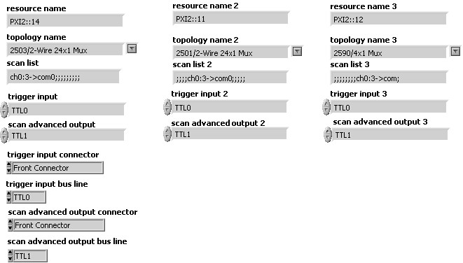
Synchronous Scanning
In this setup you are using SH9MD-AUX cable from the front of the DMM to an SCXI backplane that is connected to a switch in an SCXI-1000, SCXI-1001 or PXI-1010, or to the back of a PXI-1011. The DMM controls the SCXI switch and sends trigger to advance through the switch scanlist. Refer to the backplane section above for more information. In this configuration the switch module is controlled and triggered by the DMM using the SH9MD-AUX cable plugged into the 9 pin DIN connector labeled AUX IN on the backplane.
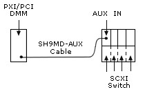
Programming SCXI Switches Using NI-DAQmx
Use DAQmx Multi Switch Sync.vi
Refer to Table 4 for switches that can be programmed under NI-DAQmx. Enter in the scan list, all the channels for each module to be scanned using the NI-DAQmx scan list syntax /Switch/channel1->channel2.
Select “/SC1Mod4/RearTrigIn” for the Advance Trigger Source if the SH9MD-AUX cable is connected to the module 4 of Chassis 1. Refer to the High Voltage SCXI Backplane section to find out which module is connected to the SH9MD-AUX cable. The DMM MC destination should be set to “External”.
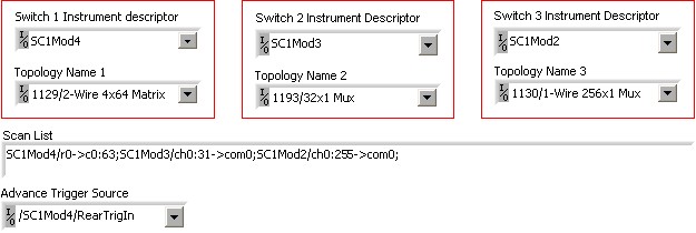
Programming SCXI Switches Using NI-SWITCH
Use niSwitch Multi switch Sync Ext.vi
This program cannot be used with the SCXI-1127 or SCXI 1128. See the Legacy Programming section below for programming these modules. Enter channels in the scan lists according to the process described in the Scan List for Multiple Switches under NI-SWITCH API section.
Add niSwitch Route Trigger Input.vi to the configuration of the switch where the SH9MD-AUX cable is connected. Refer to the High Voltage SCXI Backplane section to find out which module is connected to the SH9MD-AUX cable. Select “Rear Connector” for trigger input connector and “TTLn” for trigger input bus line. This SCXI trigger line should also be selected in Trigger Input for all switches. The DMM MC destination should be set to “external”. The SCXI-1000, SCXI-1001, and PXI-1010 only have SCXI trigger line 0 and 1 available. You can use all SCXI trigger lines in PXI-1011.
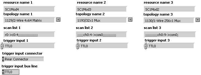
Legacy Programming for the SCXI-1127/1128 Using NI-SWITCH
Use niSwitch Multi 27_28 Sync.vi
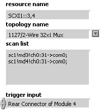
In legacy programming the chassis is configured in Traditional NI-DAQ. Enter “SCXI1::3,4” to include switch modules in slot 3 and 4 of chassis 1 in the scanning operation. Select “1127/2-wire 32x1 Mux” topology. You can select the wire mode of the modules being scanned (1-wire, 2-wire. or 4-wire) in MAX by using the channel tab in the module property. In the scan list enter the channels to be scanned as you normally would for a single module preceded by scx!mdy! x is for chassis number and y for the slot number of the switch module. The trigger input should be set to the rear connector of the module cabled to the DMM. The DMM measurement complete destination should be set to “External”.
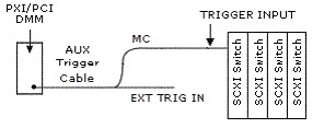
In this setup you will use an AUX trigger cable from an NI DMM to an SCXI switch. The Switches are controlled by another device. SCXI switches can receive an input trigger from the front panel or terminal block. Connect the MC signal from the DMM to the appropriate external trigger input terminal on the front panel or in the terminal block of one SCXI switch.
Programming SCXI Switches Using NI-DAQmx
Use DAQmx Multi Switch Sync.vi
Refer to Table 4 for switches that can be programmed under NI-DAQmx. Enter in the scan list, all the channels for each module to be scanned using the NI-DAQmx scan list syntax /Switch/channel1->channel2.
Select “/SC1Mod4/TrigIn” for the Advance Trigger Source if the AUX trigger cable from the DMM is connected to the front panel or the terminal block of module 4. The DMM MC destination should be set to “External”.
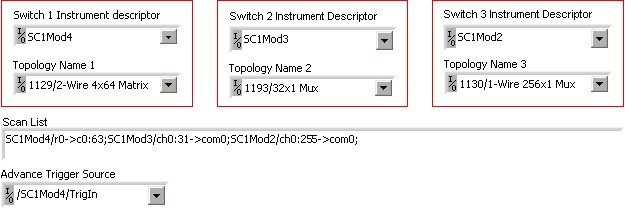
Programming SCXI Switches Using NI-SWITCH
Use niSwitch Multi Switch Sync Ext.vi
This program cannot be used with the SCXI-1127 or SCXI 1128. See the Legacy Programming section below for programming these modules. Enter channels in the scan lists according to the process described in the Scan List for Multiple Switches under NI-SWITCH API section.
Add niSwitch Route Trigger Input.vi to the configuration of the switch where the AUX trigger cable is connected. Select “Front Connector” for trigger input connector and “TTLn” for trigger input bus line. This SCXI trigger line should also be selected in Trigger Input for all switches. The DMM MC destination should be set to “external”. The SCXI-1000, SCXI-1001, and PXI-1010 only have SCXI trigger line 0 and 1 available. You can use all SCXI trigger line in the PXI-1011.
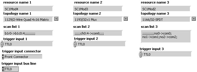
Legacy Programming for the SCXI-1127/1128 Using NI-SWITCH
Use niSwitch Multi 27_28 Sync.vi
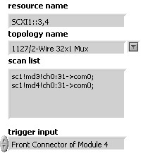
In legacy programming the chassis is configured in Traditional NI-DAQ. Enter “SCXI1::3,4” to include switch modules in slot 3 and 4 of chassis 1 in the scanning operation. Select “1127/2-wire 32x1 Mux” topology. You can select the wire mode of the modules being scanned (1-wire, 2-wire. or 4-wire) in MAX by using the channel tab in the module property. In the scan list enter the channels to be scanned as you normally would for single module preceded by scx!mdy! x is for chassis number and y for the slot number of the switch module. The trigger input should be set to the front connector of the module connected to the DMM. The DMM measurement complete destination should be set to “External”.
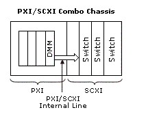
In this setup you are using a PXI/SCXI combination chassis. You need to place you PXI DMM in the right most slot. You do not need any cables between the PXI DMM and the SCXI Switches to control and trigger the SCXI switches. In the combination chassis, the right most slot of the PXI chassis has several internal lines available for SCXI communication and 2 internal trigger lines (TTL0 and TTL1) connected to SCXI trigger lines (SCXI Trig0 and SCXI Trig1).
Programming SCXI Switches Using NI-DAQmx
Use DAQmx Multi Switch Sync.vi
Refer to Table 4 for switches that can be programmed under NI-DAQmx. Enter in the scan list, all the channels for each module to be scanned using the NI-DAQmx scan list syntax /Switch/channel1->channel2.
For Advance Trigger Source select SCXI_Trig0 from any SCXI module. In our example, we selected “/SC1Mod1/SCXI_Trig0”. The DMM MC destination should be set to “LBR Trig 0” for NI 407x or to “TTL0” for NI 4060.

Programming SCXI Switches Using NI-SWITCH
Use niSwitch Multi Switch Sync Int.vi
This program cannot be used with the SCXI-1127 or SCXI 1128. See the Legacy Programming section below for programming these modules. Enter channels in the scan lists according to the process described in the Scan List for Multiple Switches under NI-SWITCH API section.
All trigger inputs should be set to “TTL0”. The DMM MC destination should be set to “LBR Trig 0” for NI 407x or to “TTL0” for NI 4060.

Legacy Programming for the SCXI-1127/1128 Using NI-SWITCH
Use niSwitch Multi 27_28 Sync.vi
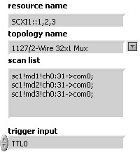
In legacy programming the chassis is configured in Traditional NI-DAQ. Enter “SCXI1::1,2,3” to include switch modules in slot 1, 2 and 3 in chassis 1 in the scanning operation. Select “1127/2-wire 32x1 Mux” topology. You can change the wire mode of the modules being scanned (1-wire, 2-wire. or 4-wire) in MAX by using the channel tab in the module property. In the scan list enter the channels to be scanned as you normally would for single module preceded by scx!mdy! x is for chassis number and y for the slot number of the switch module. The trigger input should be set to the “TTL0”. The DMM measurement complete destination should be set to “LBR Trig 0”.
Handshaking
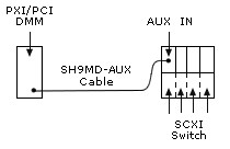
In this setup you are using SH9MD-AUX cable from the front of an NI-407x to an SCXI backplane connected to a switch in an SCXI-1000, SCXI-1001 or PXI-1010, or to the back of a PXI-1011. Refer to the High Voltage SCXI backplane section for more information. In this configuration the switch module is controlled and triggered by the NI-407x using the SH9MD-AUX cable plugged into the 9 pin DIN connector labeled AUX IN on the backplane.
Programming SCXI Switches Using NI-DAQmx
Use DAQmx Multi Switch Hand.vi
Refer to Table 4 for switches that can be programmed under NI-DAQmx.
NOTE: If the SCXI chassis is not a PXI-1011, this program can not be used with SCXI-1127 or SCXI-1128. These two modules can only send their Advance Complete trigger to SCXI trigger “TTL 2”, available only in the PXI-1011. If the SCXI-1127, SCXI-1128 or SCXI-1129 are included in the switches to be scanned, they cannot be the modules cabled to the SH9MD-AUX.These modules cannot send their Advance Complete trigger the rear connector.
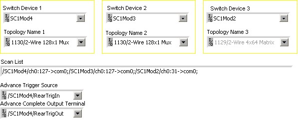
Enter in the scan list, all the channels for each module to be scanned using the NI-DAQmx scan list syntax /Switch/channel1->channel2.
Select “/SC1Mod4/RearTrigIn” for the Advance Trigger Source and “/SC1Mod4/RearTrigOut/ for Advance Complete Output Terminal if your SH9MD-AUX cable is connected to the 4 of chassis 1. Refer to the High Voltage SCXI Backplane section to find out which module is connected to the SH9MD-AUX cable. The NI 4060 cannot be used in this setup. The NI 407x MC destination should be set to “External” and the trigger source to “Aux Trig 1”. This selection is only available with NI-DMM 2.2 or later for the NI 407x.
Programming SCXI Switches Using NI-SWITCH
Use niSwitch Multi Switch Hand Ext.vi
NOTE: This program cannot be used with SCXI-1127, SCXI-1128. If the SCXI-1129 is included in included in the switches to be scanned, it cannot be the module connected to the SH9MD-AUX cable. This module cannot send its SA to the rear connector.
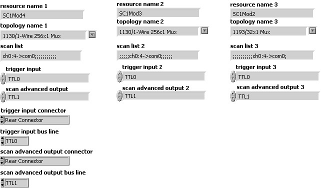
Enter channels in the scan lists according to the process described in the Scan List for Multiple Switches under NI-SWITCH API section.
Add niSwitch Route Trigger input.vi and niSwitch Route Scan Advanced Output.vi before the niSwitch commit.vi of the switch where the SH9MD-AUX cable is connected. Refer to the High Voltage SCXI Backplane section to find out which module is connected to the SH9MD-AUX cable. Select “Rear Connector” for Trigger input connector, and for Scan Advanced output connector. Select “TTL0” for Trigger input bus line, and for Trigger Input of all the switches. Select “TTL1”for Scan Advanced Output Bus Line and for Scan Advanced Output of all the switches The NI 4060 cannot be used in this setup. The NI 407x MC destination should be set to “External” and the trigger source to “Aux Trig 1”. This selection is only available with NI-DMM 2.2 or later for the NI 407x.
SCXI switches can receive/send triggers from/to the front panel or terminal block. In this setup you will use an AUX trigger cable. Connect the MC cable from the DMM to the appropriate external trigger input terminal (ext trig in) on the front panel or in the terminal block of one SCXI switch and connect the EXT TRIG IN of the DMM to the scanner advanced terminal on the front panel or terminal of the same switch.
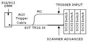
Programming SCXI Switches Using NI-DAQmx
Use DAQmx Multi Switch Hand.vi
Refer to Table 4 for switches that can be programmed under NI-DAQmx.
NOTE: If the SCXI chassis is not a PXI-1011, this program can not be used with SCXI-1127 or SCXI-1128.
Enter in the scan list, all the channels for each module to be scanned using the NI-DAQmx scan list syntax /Switch/channel1->channel2.
Select “/SC1Mod4/TrigIn” for the Advance Trigger Source and “/SC1Mod4/TrigOut/ for Advance Complete Output Terminal if the AUX trigger cable is connected to the front panel or terminal block of module 4 in chassis 1. The DMM MC destination should be set to “External” and the trigger source to “External”.
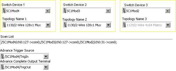
Programming SCXI Switches Using NI-SWITCH
Use niSwitch Multi Switch Hand Ext.vi
NOTE: This program cannot be used with SCXI-1127 or SCXI-1128.
Enter channels in the scan lists according to the process described in the Scan List for Multiple Switches under NI-SWITCH API section.
Add niSwitch Route Trigger input.vi and niSwitch Route Scan Advanced Output.vi before the niSwitch commit.vi of the switch where the AUX trigger cable is connected. Select “Front Connector” for Trigger input connector, and for Scan Advanced output connector. Select “TTL0” for Trigger input bus line, and for Trigger Input of all the switches. Select “TTL1”for Scan Advanced Output Bus Line and for Scan Advanced Output of all the switches. Select “External” for Measurement Complete Destination and for Trigger source in the DMM configuration.
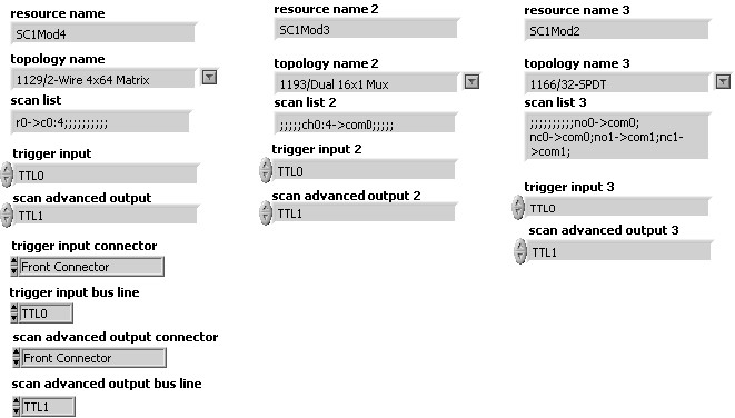
In this setup you are using a PXI/SCXI combination chassis. You need to place you PXI NI-407x in the right most slot. Only the NI 407x is able to handshake with SCXI switch module in this configuration. You do not need any cables between the PXI DMM and the SCXI Switches to control and trigger them.
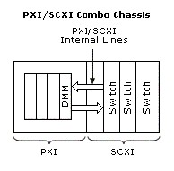
Programming SCXI Switches Using NI-DAQmx
Use DAQmx Multi Switch Hand.vi
Refer to Table 4 for switches that can be programmed under NI-DAQmx.
NOTE: This program cannot be used with the SCXI-1127 or SCXI 1128.
Enter in the scan list, all the channels for each module to be scanned using the NI-DAQmx scan list syntax /Switch/channel1->channel2.
For Advance Trigger Source and Advance Complete Output Terminal, select SCXI_Trig0 and SCX_Trig1 respectively from any module. In our example, we selected “/SC1Mod1/SCXI_Trig0” and “/SC1Mod1/SCXI_Trig1”. The NI 4060 cannot be used in this setup. The NI 407x MC destination should be set to “LBR Trig 0” and the trigger source to “LBR Trig 1”. This selection is only available with NI-DMM 2.2 or later for the NI 407x.
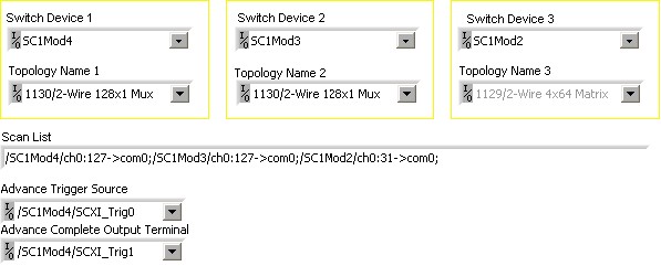
Programming SCXI Switches Using NI-SWITCH
Use niSwitch Multi Switch Hand Int.vi
NOTE: This program cannot be used with SCXI-1127 or SCXI-1128.
Enter channels in the scan lists according to the process described in the Scan List for Multiple Switches under NI-SWITCH API section.
The trigger input for all switches should be set to “TTL0” and the scan advanced output should be set to “TTL1”. The NI 4060 cannot be used in this setup. The NI 407x MC destination should be set to “LBR Trig 0” and the trigger source to “LBR Trig 1”. This selection is only available with NI-DMM 2.2 or later for the NI 407x.
