NI does not actively maintain this document.
This content provides support for older products and technology, so you may notice outdated links or obsolete information about operating systems or other relevant products.
The trigger signals to which DAQ hardware responds are classified in two ways: analog and digital.
Figure 2. Digital Trigger
Triggered data acquisition applications can be classified in two ways: posttriggered and pretriggered.
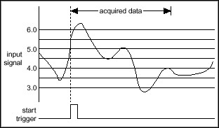
Figure 4. Pretriggered Acquisition
This application note focuses on implementing various types of triggered applications using National Instruments DAQ hardware and NI-DAQ driver software. NI-DAQ provides a powerful, yet easy-to-use interface for developing sophisticated DAQ applications from a variety of programming environments, such as LabVIEW, Measurement Studio, C++ and Visual Basic. To develop DAQ applications in LabVIEW, use the Data Acquisition VIs from the LabVIEW functions palette. In other programming environments, make function calls within the NI-DAQ DLL. Details about the Data Acquisition VIs and NI-DAQ functions can be obtained from the online documentation that is shipped with LabVIEW and NI-DAQ, respectively. Sample DAQ programs illustrating several of the concepts discussed in this document can be found in the LabVIEW/examples/daq and NIDAQ/samples directories.
DAQ applications typically consist of the four building blocks shown below (Figure 5).
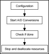
Trigger conditions for any application are specified in the configuration section by calling the appropriate Traditional NI-DAQ (Legacy) functions or Data Acquisition VIs in LabVIEW. The rest of this document discusses how to implement various triggering types using LabVIEW and Traditional NI-DAQ (Legacy) functions.
A. Posttriggered Acquisition with a Digital Start Trigger
In a posttriggered acquisition, the A/D conversions start after the DAQ hardware receives the trigger signal. The digital trigger is typically wired to the external trigger input of the I/O connector of the specified device.
The following code snippet shows how to set up a posttriggered application using NI-DAQ functions:
/* Specify that a trigger is being used */
DAQ_Config (deviceNumber, startTrig, extConv );// set startTrig = 1
/* Start the acquisition */
DAQ_Start (deviceNumber, …)
Note: The code snippets using NI-DAQ functions are not complete programs; they only show the functions necessary to set up a particular triggered operation.
Figure 6 illustrates how to set up a digital posttriggered acquisition in LabVIEW.
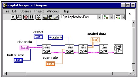
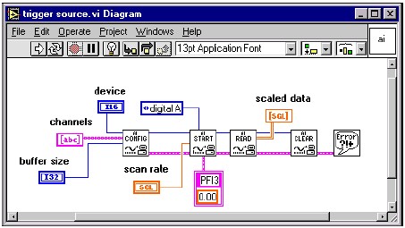
With the National Instruments E Series multifunction I/O (MIO) devices, you can choose from one of 10 different lines (labeled PFI0-9 on the I/O connector) as the trigger input. The default trigger source is PFI0, but an alternate trigger source (e.g., another PFI line or RTSI line) can be selected by calling the Traditional NI-DAQ (Legacy) function Select_Signal.
The following code snippet shows how to set the trigger source to be the falling edge of a TTL signal wired into the PFI3 pin on the I/O connector:
/* Select trigger source */
Select_Signal(deviceNumber, ND_IN_START_TRIGGER, ND_PFI_3, ND_HIGH_TO_LOW);
/* specify that a start trigger is to be used */
DAQ_Config(deviceNumber, startTrig, extConv); // set startTrig = 1
/* start the acquisition */
DAQ_Start(deviceNumber, …)
Alternately, you can use the Scan_Start function to read from multiple channels.
Figure 7 illustrates how to specify an alternate trigger source in the AI Start.vi in LabVIEW.
B. Pretriggered Acquisition on a Digital Stop Trigger
In a pretriggered acquisition, the A/D conversions are initiated with a software function call. Traditional NI-DAQ (Legacy) stores the digitized data in computer memory in a circular buffering scheme, replacing the oldest points in the buffer with the new samples. Once the trigger signal is received, a specified number of points before and after the trigger are returned to the calling application (e.g., LabVIEW, C++, etc.) by Traditional NI-DAQ (Legacy).
The following code snippet shows how to configure a pretriggered acquisition using Traditional NI-DAQ (Legacy) function calls:
/* Configure pretriggered acquisition */
DAQ_StopTrigger_Config (deviceNumber, stopTrig, ptsAfterStopTrig );
// Set stopTrig to 1.
// Set ptsAfterStoptrig to (total scans - # of pretrig scans).
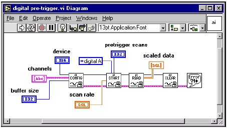
Figure 8 illustrates how to create a pretriggered application in LabVIEW by specifying the desired number of pretrigger scans in AI Start.vi. Note that setting the pretrigger scans to zero creates a posttriggered acquisition.
C. Pretriggered Acquisition with Start and Stop Triggers
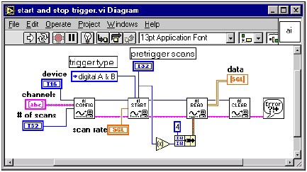
You can also set up an acquisition that uses both start and stop triggers. In this case, a digital or analog trigger starts the acquisition instead of a software function. Once the acquisition starts, a circular buffering scheme (similar to the previous case) is implemented until the stop trigger signal is received. The data returned consists of the specified number of pretrigger and posttrigger samples relative to the stop trigger signal (Figure 4).
E Series devices use PFI0 as the default start trigger input and PFI1 as the default stop trigger input. An alternate trigger source can be selected by calling the Trigger Config.vi in LabVIEW. The following code snippet shows how to call the Select_Signal function in Traditional NI-DAQ (Legacy) to select an alternate trigger source:
/* specify a start trigger */
DAQ_Config (board, startTig, extConv ); // Set startTrig to 1.
/* specify a stop trigger */
DAQ_StopTrigger_Config (board, stopTrig, ptsAfterStopTrig);
// Set stopTrig to 1; Set ptsAfterStoptrig to (total scans – # of pretrig scans).
On older legacy MIO boards there are dedicated STARTRIG* and STOPTRIG inputs on the I/O connector for the start and stop trigger, respectively.
Figure 9 illustrates how to implement an acquisition in LabVIEW with a start and stop trigger by specifying the trigger type in the AI Start.vi.
D. Analog Hardware Triggering
Several National Instruments E Series DAQ devices have onboard ATC that can be used to start an acquisition based on the level and slope of an analog signal. A typical application using an analog hardware trigger could be a temperature-monitoring system where the acquisition starts only when the temperature rises above a certain value. The trigger signal can be wired to either the PFI0 pin or to an analog input channel.
Analog hardware trigger conditions can be set by the following Traditional NI-DAQ (Legacy) function:
Configure_HW_Analog_Trigger (deviceNumber, onOrOff, lowValue, highValue, mode, trigSource);// set onOrOff = ND_ON
The lowValue and highValue parameters specify the levels to use for triggering. Details about the valid values for these and other parameters for the function can be found in the Traditional NI-DAQ (Legacy) Function Reference Online Help, which ships with NI-DAQ.
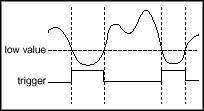
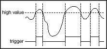
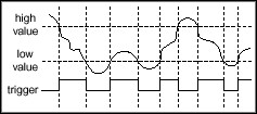
The following paragraphs describe the available modes and trigger-generation scenarios, and the figure following each paragraph illustrates that situation. Values specified by highValue and lowValue are represented using dashed lines, and the signal used for triggering is represented using a solid line.
ND_BELOW_LOW_LEVEL—The trigger is generated when the signal value is less than the lowValue. HighValue is unused.
ND_ABOVE_HIGH_LEVEL—The trigger is generated when the signal value is greater than the highValue. LowValue is unused.
ND_INSIDE_REGION—The trigger is generated when the signal value is between the lowValue and the highValue.
ND_HIGH_HYSTERESIS—The trigger is generated when the signal value is greater than the highValue, with hysteresis specified by lowValue.
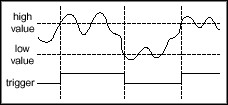
ND_LOW_HYSTERESIS—The trigger is generated when the signal value is less than the lowValue, with hysteresis specified by highValue.

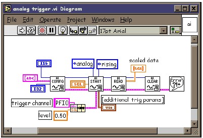
Figure 10 illustrates how to specify the appropriate parameters in the AI Start.vi to implement analog hardware triggering in LabVIEW.
E. Conditional Retrieval
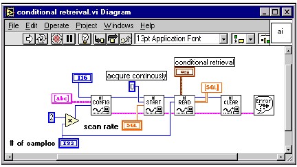
If your hardware does not implement analog hardware triggering, you can implement a form of analog triggering known as “conditional retrieval.” Here, Traditional NI-DAQ (Legacy) transfers the acquired samples to a buffer in computer memory using a circular buffering scheme, checking each sampled point to determine if it satisfies user-specified voltage and slope conditions. When the trigger conditions are met, Traditional NI-DAQ (Legacy) returns the data to the calling application. The key difference between “analog hardware triggering” and “conditional retrieval” is the fact that the former is done by the ATC in hardware while Traditional NI-DAQ (Legacy) implements the latter in software.
Conditional retrieval is implemented in Traditional NI-DAQ (Legacy) using the function Config_ATrig_Event_Message:
Config_ATrig_Event_Message (deviceNumber, mode, chanStr, trigLevel, windowSize, trigSlope, trigSkipCount, pretrigScans, postTrigScans, handle, message, callbackAddr)
The driver generates a Windows message or executes a user-specified callback function when the trigger conditions are satisfied. Please refer to the National Instruments Developer Zone Online Application Note, Using DAQ Event Messaging Under Windows NT/95, for details on setting up the event message functions using Traditional NI-DAQ (Legacy) functions.
Figure 11 illustrates how to specify in the cluster input in the AI Read.vi to implement conditional retrieval in LabVIEW.
F. Synchronizing Several DAQ Devices
National Instruments DAQ hardware for PCI and ISA have the RTSI bus, with which two or more devices installed in the same computer can share certain timing and triggering signals. A RTSI bus cable connects to each device so that each device can either send or receive the signal from one of seven available lines (RTSI0-RTSI6) on the RTSI bus. A common application involving multiple devices is simultaneously starting the A/D conversions on all the devices. This task can be implemented with a “master-slave” type configuration, where the “slave” devices receive the start trigger signal from the “master” device over the RTSI bus. The “master” device routes its trigger signal to one of the RTSI lines and the slave devices receive the trigger signal from the RTSI line. The slave devices must start before the master so that they can receive the trigger signal.
The following code snippet shows how to route trigger signals on E Series devices using the NI-DAQ Select_Signal function:
/* master board: send start trigger signal to RTSI_0 */
Select_Signal (masterdevice, ND_RTSI_0, ND_IN_START_TRIGGER, ND_LOW_TO_HIGH)
/* slave board: receive start trigger signal from RTSI_0 */
Select_Signal (slave_device, ND_IN_START_TRIGGER, ND_RTSI_0, ND_LOW_TO_HIGH)
/* start slave device */ DAQ_Start (slave_device, …)
/* start master device */ DAQ_Start (masterdevice, …)
You can also set up multiple slave devices by calling the Select_Signal function as necessary.
Note: The trigger signal on the master device is typically internally generated; however, you can also set up the master device to start on an external analog or digital trigger using the techniques discussed earlier.
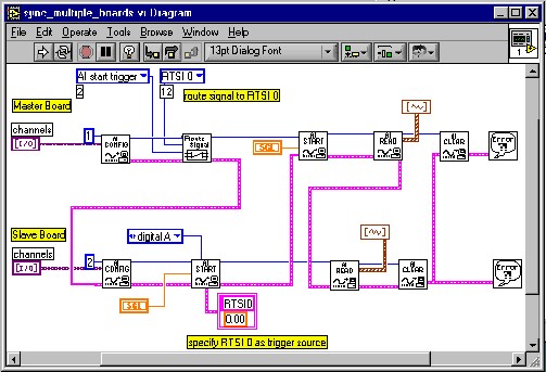
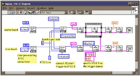
In LabVIEW, you can call the Route Signal.vi on the master device to send the start trigger signal to the RTSI line. On the slave devices, you can call the Trigger Config.vi and set up the RTSI line as the trigger source (Figure 12). You can set up as many slave configurations as necessary. The wiring scheme of the error clusters determines the execution order of the VIs and ensures that the slave devices start before the master.
The following code snippet shows how to use Traditional NI-DAQ (Legacy) functions to set up the master-slave configuration on older legacy MIO devices with RTSI bus:
/* connect EXTTRIG* line to RTSI 0 on master device*/
/* sigCode = 8 for legacy MIO devices, trigLine = 0 (for RTSI 0) and dir = 1 (transmit) */ RTSI_Conn(masterdevice,sigCode,trigLine,dir)
/* receive EXTTRIG* signal from RTSI 0 on slave device*/
/* sigCode = 8 for legacy MIO devices, trigLine = 0 (for RTSI 0) and dir = 0 (receive) */ RTSI_Conn(slavedevice,sigCode,trigLine,dir)
/* start the slave device */
DAQ_Start(slavedevice, ...)
/* start master device */
DAQ_Start(masterdevice, ...)
Figure 13 illustrates how to use the RTSI Control VIs in LabVIEW with legacy MIO devices.
G. Synchronize Analog Input and Analog Output
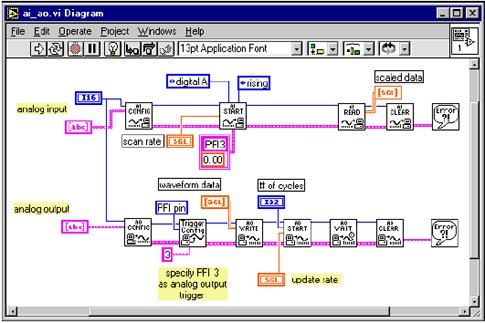
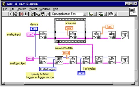
Most DAQ devices have analog output circuitry to generate analog output signals on one or more channels. A typical use of the analog output capability of the hardware is as a function generator to generate periodic waveforms (sine, square, triangle, etc.). The analog output process can be synchronized with the analog input by the following methods:
H. Event Triggering
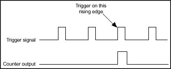
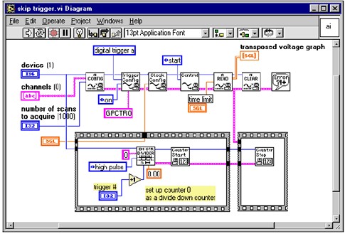
In some applications, you may want to skip a certain number of trigger pulses before starting the acquisition. This trigger type is also referred to as an “event trigger” since you are triggering on the nth (n > 1) trigger event. Such an application can be implemented using the counters on a National Instruments E Series DAQ device. The general idea is as follows:
Figure 16 shows the timing diagram associated with event triggering.
The following code snippet illustrates how to implement event triggering using Traditional NI-DAQ (Legacy) functions to start the DAQ operation on the nth trigger signal:
/* reset counter 0 */
GPCTR_Control(deviceNumber, ND_COUNTER_0, ND_RESET);
/* set counter 0 for single pulse generation */
GPCTR_Set_Application(deviceNumber, ND_COUNTER_0,ND_SINGLE_PULSE_GNR);
/* set counter 0 source to PFI 8 */
GPCTR_Change_Parameter (deviceNumber, ND_COUNTER_0,ND_SOURCE, ND_PFI_8);
/* set counter 0 to generate pulsed output */
GPCTR_Change_Parameter (deviceNumber, ND_COUNTER_0, ND_OUTPUT_MODE, ND_PULSE);
/* set low count */
GPCTR_Change_Parameter(deviceNumber, ND_COUNTER_0, ND_COUNT_1,N+1);
/* set high count */
GPCTR_Change_Parameter(deviceNumber, ND_COUNTER_0, ND_COUNT_2,N+1);
/* To output a counter pulse, you must call Select_Signal. */
Select_Signal(deviceNumber,ND_GPCTR0_OUTPUT,ND_GPCTR0_OUTPUT,ND_LOW_TO_HIGH);
/* Setup Counter 0 output as the trigger source for analog input */
Select_Signal(deviceNumber,ND_IN_START_TRIGGER,ND_GPCTR0_OUTPUT,ND_LOW_TO_HIGH);
/* Configure the Analog Input operation */
DAQ_Config(deviceNumber, iStartTrig, iExtConv);//iStartTrig = 1 DAQ_Rate(dSampRate, …) DAQ_Start(deviceNumber, …)
/* arm the counter */
GPCTR_Control(deviceNumber, ND_COUNTER_0, ND_PROGRAM);
Figure 17 shows how to implement event triggering in LabVIEW.
I. Scan Clock Gating
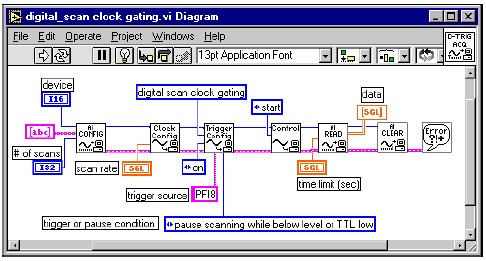
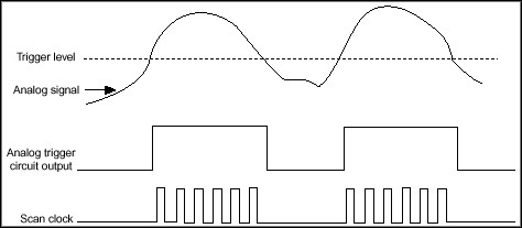
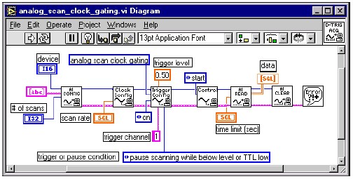
Some DAQ applications may require the user to implement a pause/resume feature where an external signal controls when the DAQ hardware performs the A/D conversions during an acquisition. For these types of applications, National Instruments DAQ devices support a feature known as “scan clock gating.” Here, the internal scan clock is gated by an external signal such that the scan clock pauses while the external signal is low and resumes when the signal goes high (or vice versa). Scan clock gating can be classified into two types, digital or analog, depending on the nature of the gate signal.

