Ni.com is currently experiencing issues that may cause some pages to fail.
Support teams are actively working on the resolution.
Ni.com is currently experiencing issues that may cause some pages to fail.
Support teams are actively working on the resolution.
This article will discuss the various features and associated concepts of NI PXI Arbitrary Waveform Generators. To learn more about NI PXI Arbitrary Waveform Generators, please see What Is a PXI Waveform Generator?
The memory architecture of most signal generators imposes restrictions on the waveform size and quantum. Every waveform downloaded to the device memory must be at least a minimum waveform size in terms of the number of samples. Additionally, the size in samples of the waveform downloaded to the device memory must be an integer multiple of a certain number or quantum.
For example, the NI 5412 arbitrary waveform generators, which has a minimum waveform size of 4 and a waveform quantum of 4, is more flexible than its predecessor which had a minimum waveform size of 256 and a quantum of 8 samples. The NI 5412 can out waveforms of size 4, 8, 12, 16, and so on, while the former could only output waveforms of size 256, 264, 272, 280, and so on.
Multiple waveforms and their waveform sequencing instructions can be loaded in the onboard memory of a signal generator. The concept of using a sequence to generate waveforms is referred to as "waveform sequencing" or "linking and looping" waveforms. Looping waveforms repeats a single waveform multiple times, while linking waveforms specifies the play list of the AWG. Because AWGs store waveforms in on-board memory, the length of the waveform is limited. Waveform looping helps generate signals with subcomponents that repeat many times. Looping a waveform segment improves memory efficiency and increases the potential duration of the waveform.
The following figures show the concepts of waveforms and segment sequencing.
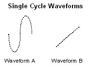
Figure 1
In Figure 1, waveform A represents a single cycle of a sine wave that is downloaded to onboard memory. Waveform B represents a single cycle of a ramp waveform that is downloaded to onboard memory. Remember that each of these waveforms must follow the minimum waveform size and quantum rules.
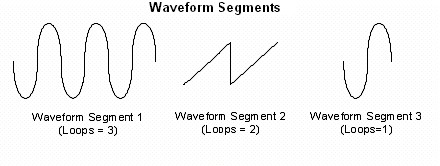
Figure 2
Segment 1, in Figure 2 above, shows a segment created using Waveform A, repeating or looping three times. Segment 2 contains Waveform B looping two times. Segment 3 contains Waveform A looping only once.
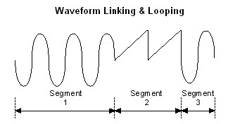
Figure 3
As seen in Figure 3, these waveforms are linked in a sequence.
Signal sources provide several types of hardware triggering for controlling your waveform generation. A trigger is an internal or external stimulus that initiates one or more device functions. Trigger stimuli include TTL digital edges, software functions, and analog levels. External triggers can be re-exported and, along with marker events (explained later), can allow you to synchronize the hardware operation with external circuitry or other NI devices. In general, signal source triggers initiate a waveform generation or cause the AWG to step from one waveform stage to another after the waveform output has begun. The following describes four commonly used trigger modes: start trigger mode, continuous trigger mode, stepped trigger mode, and burst trigger mode.
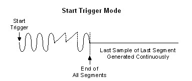
Figure 4
As shown in Figure 4, in start trigger mode the waveform sequence defined in memory generates only once by going through the entire sequence and then the waveform generation halts. After the generator receives a start trigger, the waveform generation starts at the first segment and continues through the last segment. After the entire sequence list has been generated, the last sample of the last segment is generated continuously.
On the other hand, in continuous trigger mode, the entire sequence of waveform segments is repeated continuously as shown in Figure 5. In both start trigger and continuous trigger modes, all subsequent triggers after the initial trigger are ignored.
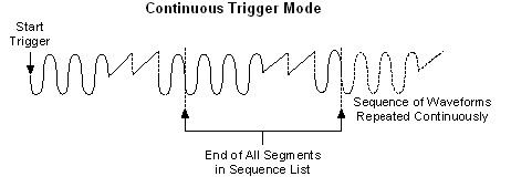
Figure 5
In stepped trigger mode, as shown in Figure 6, the waveforms defined in the sequence list generate one segment each time a trigger is recognized. The waveform will loop as many times as has been configured for that particular segment. After the generation of a segment has halted, the last sample of the waveform repeats continuously until the next trigger is received. When the next trigger is received, the waveform defined by the next segment will generate for a configured amount of loops. After the sequence list is exhausted, the waveform generation returns to the first segment and subsequent triggers will start the process again. A trigger is recognized only after the segment has finished generating. Otherwise, the trigger will be ignored.
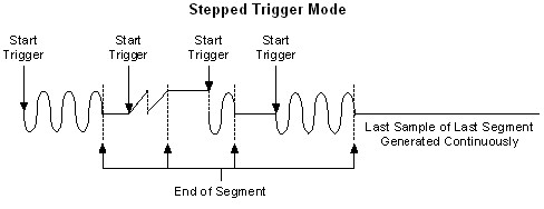
Figure 6
Burst trigger mode works very similarly to stepped trigger mode except that each waveform segment defined in the sequence list generates continuously until another trigger occurs instead of simply repeating the last sample of the last segment.
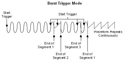
Figure 7
A marker is a digital pulse that can generate at specific points within a waveform generation. A marker can be placed in every sequence segment and used as a trigger for controlling the timing of other devices. For example, marker outputs are commonly used as a digital trigger for high speed digitizers and oscilloscopes.
Marker outputs are specified by giving an offset count (in number of samples) from the start of the waveform buffer for each segment. If the waveform loops multiple times in a segment, the marker generates each time the waveform loops at the configured sample position.
To generate a marker only once in a segment, where the waveform loops a number of times, break the segment up into multiple segments. For example, to generate a marker on only the first iteration of a sine waveform that loops 100 times, create a segment that generates the sine waveform with the marker at a specific sample position, and loops only once. Create a second segment that generates the sine waveform with no marker and loops 99 times.
As shown in Figure 8, this technique can be used in different combinations of segments to generate one marker every five loops of the sine waveform by creating a segment containing a marker and one loop (segment 1) followed by a segment with no markers that is looping four times. These two segments are repeated as long as you need to repeat the cycle.
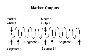
Figure 8
The biggest limitation of the standard marker output is that only one marker event can occur per waveform segment. The data marker event extends marker functionality to allow multiple marker events in one segment. Refer to the Find the Right Signal Generator guide to determine if your device supports data marker events.
A data marker is an event that allows you to export any one of the 16 waveform data bits to any valid destination on the device. Remember that an AWG converts a series of digital samples into an analog waveform using a digital-to-analog converter. For example, the NI 5421 AWG has 16 waveform data bits per sample. Up to four of the 16 waveform data bits can be exported at one time.
The digital level of a data marker event changes at the time that a specific data bit toggles in the waveform data. If the waveform data bit toggles multiple times in a segment, the data marker level changes each time. When the data bit level is high, the data marker level is high. You can also invert this relationship.
The following figure shows the exported data marker event shifting between low and high as the specified data bit toggles. On the NI 5421, data marker events can be exported to the RTSI bus, PXI trigger lines, SYNC OUT/PFI 0 and PFI 1 or PFI 4 and PFI 5.
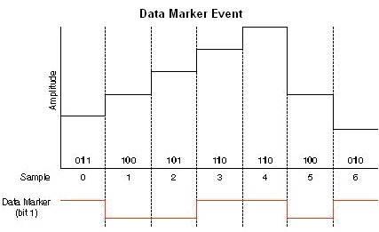
Figure 9
Data marker events allow for tighter synchronization between signal generators and other devices. For example, an AWG and a digitizer are often synchronized using the exported start trigger of the AWG. However, there exists a short delay between the time the start trigger is exported to the time analog waveform generation occurs at the output connector. When using the data marker event as the trigger source, faster trigger response times are achieved because the marker event is synchronized directly with the analog output.
Scripting is a powerful feature that allows you to quickly and easily create very complex waveform and triggering sequences. You can "link and loop" between multiple waveforms in a generation operation using a script. A script is a set of instructions that describes the waveforms to be generated, the order in which to generate them, how many times they are generated, and can even contain conditional statements. Multiple scripts can exist on the device at one time—you can choose which script to execute by referencing the script name. This section describes the syntax for creating a script, as well as how to use scripting in your applications.
To begin, let’s examine a simple script example is shown below.
When executed, this script consecutively generates three waveforms. More complex scripts can easily be created using the six primary instructions: script/end script, generate, repeat/end repeat, if/else/end if, wait, and clear.
Script/End Script - Defines a set of instructions to be contained within a single script and to associate a name with that script.
Generate - Generates a named waveform. You can generate the entire waveform or a subset of it. You can also choose to generate a marker at a specified location in the named waveform.
Repeat/End Repeat - Repeats a set of instructions. You can repeat a finite number of times, repeat forever, or repeat until a hardware Script trigger is received.
If/Else/End If - Determines what sections of a script to execute, based on whether a particular Script trigger was received.
Wait - Pauses execution until a Script trigger is received.
Clear - Ignores a previously latched Script trigger. This option is typically used before the wait until or repeat until instructions.
Let’s examine a few examples that utilize these scripting functions to create complex waveform sequences. The NI Script Editor allows users to easily write, maintain, and even error check their scripts.
Finite Repetition (N Times) - This script generates waveform1, waveform2, and then waveform3. waveform2 is repeated 3 times.
Conditional Repetition - This script generate waveform1, waveform2, and then waveform3. waveform2 repeats until scripttrigger0 occurs.
Conditional Branching - If/Then Else - This script generates waveform1. Then, if scripttrigger0 has been received wavform2 will generate. Otherwise, if scripttrigger0 has not been received waveform3 will generate.
Stepping Through Multiple Waveforms - This script generates waveform1 and then waits for scripttrigger0. Once scripttrigger0 occurs, the script generates waveform2. The script then waits for scripttrigger0 to occur again and then generates waveform3. Notice the clear instruction is used to ensure any script triggers received before the wait until instruction are ignored. This entire sequences repeat forever, until the generation is aborted.
Generating Waveforms with Markers - This script generates waveform1 and generates a marker event at sample 20.
Customers interested in this topic were also interested in the following NI products: