The Fundamentals of Restbus Simulation
Overview
Contents
- National Instruments Tools for Restbus Simulation
- The 8 Fundamental Techniques for Restbus Simulation
- Conclusion
- Additional Resources
National Instruments Tools for Restbus Simulation
This paper often refers to several NI hardware and software tools you can use for typical restbus simulation applications and strategies. These tools can help you achieve the functionality required for restbus simulation and can greatly reduce the time you need for application-specific configuration:
- NI-XNET CAN, LIN, and FlexRay Interfaces: High-performance CAN, LIN, and FlexRay interfaces for transmitting and receiving bus traffic.
- NI VeriStand: A powerful out-of-the-box software tool for performing real-time testing applications more efficiently.
- NI VeriStand Stimulus Profile Editor: A tool for creating real-time test scripts and sophisticated real-time sequences that include decision making, multitasking, and complex mathematical functions.
- NI Vehicle Communication Software Suite: AUTOSAR compatible, supports multiple automotive protocols, and simplifies ECU variant testing with minimal programming. It offers seamless restbus simulation, diagnostics, calibration, and web-based configuration.
The 8 Fundamental Techniques for Restbus Simulation
You can accomplish many different applications and tasks using restbus simulation, but most of these stem from eight different techniques and fundamental building blocks that you can use in several ways. The remainder of this paper explores these eight tasks in more detail and describes ways you can implement them using the tools mentioned above.
1. Switching Between Real and Simulated ECUs
As mentioned earlier, you can use restbus simulation to simulate all or part of an in-vehicle network. Because of this, a desired functionality in these types of applications is the ability to easily replace a simulated ECU with a real ECU, or vice versa, for simulating different parts of the full network. Since a large number of ECUs can communicate on the same network, this transition from real to simulated or simulated to real must be as easy as possible and seamless.
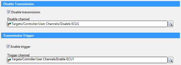
Figure 1: Use NI VeriStand with NI-XNET interfaces to quickly switch between simulating a real ECU and allowing for a real ECU to be on the bus.
NI-XNET vehicle bus interfaces and NI VeriStand help you easily accomplish this task. By setting up disable and enable triggers for specific traffic on the bus, you can easily toggle between transmission and no transmission of the network communication to simulate an ECU or having the actual ECU on the network. This technique can be applied to the entire CAN, LIN, or FlexRay port or just a single frame at a time depending on how much communication you want to simulate.
2. Network Simulation Model Importing
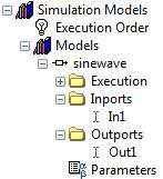
You can interact with models from a variety of modeling environments and programming languages using NI VeriStand. It can run compiled models created in any supported modeling environment as well as uncompiled models (.mdl files) created using The MathWorks, Inc. Simulink®1 software. You can then map the inports and outports of these models to incoming or outgoing messages for the NI-XNET devices.
Figure 2: An example sine wave model has been imported into NI VeriStand for network communication.
[1] Simulink® is a registered trademark of The MathWorks, Inc.
3. Custom Network Communication Scripting
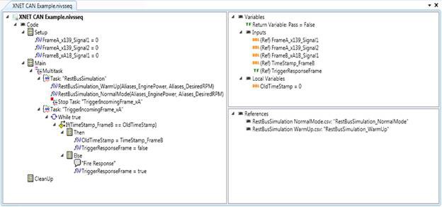
In addition to using models for network communication, you may need to write custom scripts for network communication to perform specific tasks. Unlike transmitting a cyclic message at a desired rate, for scripting you often must transmit a specific pattern or profile onto the bus. Using the NI VeriStand Stimulus Profile Editor, you can develop specific profiles and sequences to allow for a desired profile of network communication to be transmitted onto the bus for testing an ECU's response to known stimuli.
Figure 3: Create a stimulus profile for network communication using the NI VeriStand Stimulus Profile Editor.
4. Message Transmission Queuing
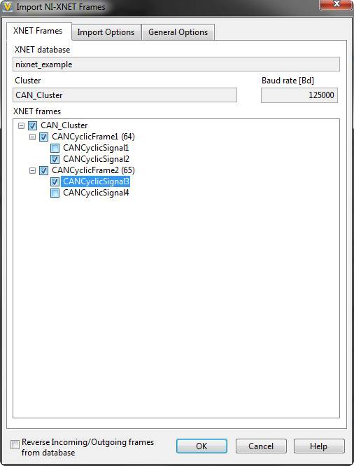
In contrast to creating a profile of a specific message or series of messages, message transmission queuing often requires you to set up a certain order of different network messages to be transmitted along with triggers for each one. You can use the NI VeriStand Stimulus Profile Editor for this purpose as well. With the same tool and environment that you use for custom scripting, you can queue up network messages in a specific order and configure transmission triggers for each frame. If the only queuing you need is to transmit a cyclic message at a desired rate, you can configure this in the NI VeriStand System Explorer and automatically import the message from network databases like FIBEX and .DBC files.
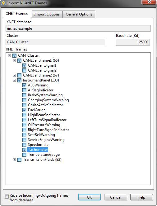
Figure 4: Use the NI VeriStand environment to automatically parse network databases for configuring the transmission of cyclic frames.
5. Manual Message Transmission
You also may need to send event-driven messages that can be sent on demand or when a trigger condition is met. You can apply the same tools you use for cyclic transmission to the manual transmission of event messages.
Figure 5: Also use the NI VeriStand environment to parse a network database to help configure the transmission of event-driven messages.
6. Log File Data Replay
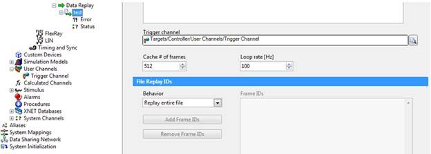
With the same steps you used to transmit previously recorded bus traffic exactly as it was originally communicated, you can effectively test ECU software changes and monitor a response to a known stimulus. Using the NI VeriStand System Explorer, you can configure recorded vehicle network log files to be transmitted exactly as they were recorded. You also can configure the file replay with user-specific settings such as setting up a trigger condition to start the replay, including frames to transmit or excluding frames from transmitting.
Figure 6: Configure a recorded log file to be transmitted using NI VeriStand and NI-XNET interfaces.
7. Trigger Conditions for Communication
By combining NI VeriStand tools with NI-XNET interfaces, you can achieve several powerful options for communication triggering. This document referred to many of these options when discussing trigger conditions that can be configured for many of the other restbus simulation fundamentals. In addition, you can choose from several trigger sources including value changes, specific messages, user-specific channels, and other I/O.
8. Test Creation and Report Generation
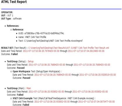
Simply performing the simulation is not the whole process. You also need to summarize the results and conduct tests to see if the device is performing as expected. You can use the NI VeriStand Stimulus Profile Editor to develop custom pass/fail tests and generate reports in a standard format such as ATML to show and share test results.
Figure 7: Use the NI VeriStand Stimulus Profile Editor to create customizable tests and reports for sharing results.
Conclusion
A testing technique like restbus simulation for ECU software validation can be a valuable method to save time and money in the long run, but it also involves several specific components and techniques. Understanding restbus simulation fundamentals and the tools for efficient testing can decrease your application development time while helping you find bugs earlier. NI hardware and software tools like NI VeriStand, the NI VeriStand Stimulus Profile Editor, and NI-XNET vehicle bus interfaces equip you with the tools you need to completely customize your restbus simulation applications quickly.
Simulink® is a registered trademark of The MathWorks, Inc. Other product and company names listed are trademarks and trade names of their respective companies.

