TrainSim: A Digital Vehicle Twin of a Train
George Kaehler, Siemens AG Mobility Division
Case Study Highlights
Results:
Achieved greater than 90 percent reduction in new product commissioning time
Hundreds of thousands of Euros saved
Most faults now detected well in advance of production

“When you put PXI, C Series, VeriStand, and LabVIEW together, they deliver the most complete ecosystem available on the market.”
- George Kaehler, Siemens AG Mobility Division
The Challenge:
Siemens needed the ability to test every component of a new train earlier in the development process to get their highly complex products to market quickly at a competitive price, without fear of quality reduction.
The Solution:
The development of a complete, modular digital twin of the train and the environment upon which every component could be tested with a fully simulated or HIL methodology. Siemens maintains more than 500 test benches that use NI hardware and software.
Author(s):
George Kaehler, Siemens AG Mobility Division
Siemens Uses Digital Twin to Accelerate Validation of Train Designs
Introduction
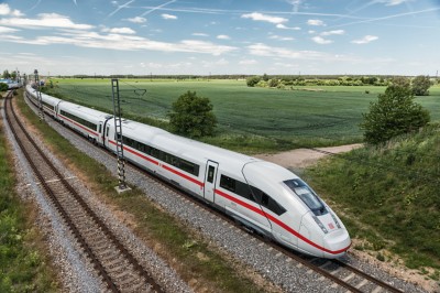
In 1879, Werner von Siemens invented the first electric locomotive. Today, Siemens Mobility is one of the world’s largest providers of high-quality rolling stock and rail infrastructure meeting the needs of an industry that is growing because of the global desire for electrified, eco-friendly and efficient transportation. Because today’s customers want flexible vehicle platforms that can be reconfigured to meet their unique needs, we must deliver these platforms quicker than ever before—while ensuring the highest quality standards.

Accelerating Product Development through Virtualization of Test
Previously, an industry-acceptable commissioning period for a new train type was at least six months, if not longer. This was due to the extensive physical testing required that can cost an estimated $10,000 a day. Any delay incurred here from unplanned test introduces risk of late customer delivery that not only degrades trust but can also result in high contractual fines.
Our vision at Siemens is to be able to deliver complex train systems that meet the needs of our customers and deliver significantly more value to our customers. As physical test time scales over proportionally to the complexity and novelty of the new system, to avoid long delays we knew a new approach was required.
Our goals were to:
- Reduce the overall cost of test and make it more predictable to support accurate time, resource and budget forecasts
- Reduce test time to meet short delivery deadlines and bring new technology to market more quickly
- Maintain quality despite growing product complexity
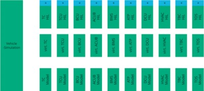
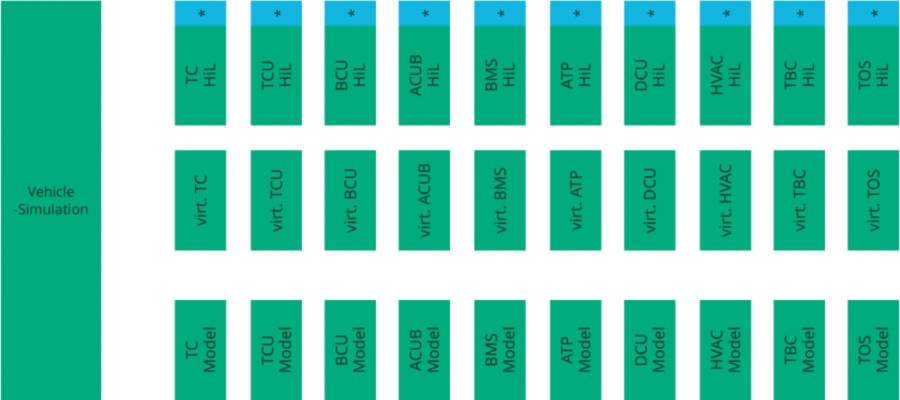
For these reasons, Siemens adopted a simulation strategy building a simulated “TrainSim,” where every electronic and software component can be tested before being built into the product. The TrainSim takes this one step further with digital representations of every component, allowing engineers to test their software “on a real train” without ever stepping away from their laptop. The TrainSims run within a full simulated environment or “TrackSim” which can provide accurate representation of every scenario the train may encounter from geographical topology to degraded GPS signals in tunnels and even slippery rails caused by leaves and weather.
Application Approach
Our strategy centers on the concept of digital twinning. A large library of models represents the characteristics of each train component (software, hardware, communications, and schematics). Where our approach differs from conventional methodologies is that we moved from monolithic architecture to modular architecture. Instead of creating a single model that represents the entire vehicle, we focus on meticulously designing or modeling even the smallest components, such as electromechanical switches, to large devices and controllers. Using this library of hundreds of components, we can now “build” a digital train from the ground up in sync with the vehicle development teams. Each night, we incorporate all the latest developments, allowing us to provide developers with the current state of vehicle development. This cycle ensures that they have up-to-date information every day, which is crucial for effective implementation of this solution.
This approach has added benefits such as the ability to easily retest components with historical states of development which helps pinpoint faults. We can also “cut” the train at any point allowing real hardware to be tested at a component, subsystem, or system level just as easily.
To deliver this system, we maintain more than 500 distinct test benches and systems, each running various software configurations and with different pieces of hardware. And, every component can be debugged in real time with tens of thousands of configurations.
Standardization is central to managing such a large and complex test infrastructure, and we employ standard templates across all aspects of our design to streamline the process of creating rules and debugging within our intricate system. Given the complexity of the application, no single engineer can oversee it entirely. Through these standards, we promote transparency, enabling multiple individuals to contribute effectively. Furthermore, ongoing maintenance and governance tasks ensure consistent quality throughout the architectural development process.
Despite the high level of upfront investment in creating the complex library of models and test benches this approach has proven to be an effective and cost-efficient business model for test. We know that the savings in development time, physical test, product quality, and delivery schedule have paid for the program many times over.
Cross-Functional Collaboration
Key to the success of this project beyond the technology has been our commitment to collaborating with engineers from across the design process. To add value, you cannot focus on just one task in a silo—but you must understand the value of each task throughout the product design workflow, optimizing for each one…and the transfers between them. As a test team, we have earned a seat at the table in product design meetings through listening, engagement, and continuously striving to understand the needs of engineers rather than imposing our views upon them. This involvement has accelerated the adoption of HIL and digital twin methodologies within product groups.
This trust allows our small team of engineers to service a large number of product groups. Each team can specialize, optimizing towards excellence in their field: the design teams in their system, us in the digital vehicle twin—and NI in test software and equipment. When everyone trusts each other to play their position the team is stronger.
Use of NI Tools and Ecosystem
At Siemens, we want our engineering group to focus on the design of better products, not on recreating industry standards in test infrastructure. We have chosen the NI platform, as it provides the most comprehensive set of I/O, embedded controllers and test development software on the market. We use thousands of NI modules in hundreds of NI chassis each connected to NI test software. What’s more, NI’s open architecture gives the flexibility to bring in third-party components or even develop our own custom elements if required.
- NI LabVIEW is our first choice for development as the graphical language and complete environment is intuitive and productive to use. Our main use case here is in developing individual models of components.
- NI VeriStand provides a simulation environment where we can exchange a simulated component with a real one just by changing the signal mapping. The key advantage lies in the adaptability and openness of this ecosystem integrating closely with LabVIEW, MathWorks® Simulink® software, and other languages.
- The PXI platform provides the instruments we need in a small, high channel density form factor that we can rely on.
- NI CompactDAQ hardware provides a small, rugged solution for conditioned measurements. Its easy integration with LabVIEW makes it a common choice throughout our lab.
System Success
Our modular train simulation is a first in the industry and delivers significant value to our customers. Trains can be as complex as passenger aircraft, but are produced in a low-volume, high-mix environment as every customer has unique requirements. Our high-quality digital twin test strategy:
- Lowers costs as it identifies problems early in the design process before they become systemic: this potentially saves a fortune in physical test and late-stage product redesigns
- Shortens time to market with design verification commissioning reduced to just a few weeks: this is a significant improvement
- Improves quality by identifying corner case defects that would not have been detected with traditional or physical tests
Our ability to test virtually every new configuration of components allows us to bring highly complex, highly customized products to market quickly without fear of quality reduction, and at a competitive price.
Future Development
Our goal is to supply digital twins of our vehicles not only for our whole company, our customers, and our suppliers—from the first ideas right up until the decommissioning of the vehicle. Our ability to introduce test earlier in the design cycle will contribute to defects being detected as early as possible in the design process that will improve train quality, save time, and save money. To achieve this goal, we must scale our model access to thousands of engineers at Siemens and potentially thousands more at our suppliers, maintenance groups, partners and customers.
Access to a simulated test environment for every engineer to use for development will result in a better and more reliable train and more satisfied customers and users of our products.
Author Information:
George Kaehler,
Siemens Mobility GmbH