Flare Measurement System: Automating Steel Inspection with NI LabVIEW
Marcin Polaszyk, TBG-SOLUTIONS
"The solution will benefit our client in more than one way as the vast amount of data acquisition will produce quality information available for reviewing. The customer can improve the quality of their steel and become increasingly more competitive in the British steel industry."
- Marcin Polaszyk, TBG-SOLUTIONS
The Challenge:
We aimed to create an accurate and expandable inspection system for a steel production line. The system needed to be more efficient, faster, and less prone to error than the current method of human inspection.
The Solution:
We used LabVIEW software and a third-party laser scanner, linear actuator, and a wheel encoder to create an inspection system capable of continuous 3D surface mapping for accurate inspection of flare defects. The system could also store raw and flare data for future purposes.

Introduction
Inspecting steel for flaring is an important stage of the steel production cycle. The inability to inspect for flaring increases the probability of the final product failing quality control, which results in the waste of used steel. In the current system, an employee visually inspects a continuous stream of steel strips to identify flares and estimate their dimensions. The employee adjusts a cutting blade to remove the defect. This method can be wasteful, time consuming, and prone to human error. The customer required a software and hardware solution to automate the inspection stage and improve this process. They chose TBG Solutions, an NI Partner, to address the issue.
System Overview
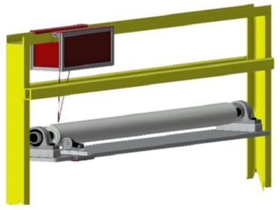
Our system consists of a laser scanner located above the production line, where it acquires surface measurements of the steel strip passing beneath it. It is situated on a linear actuator so the system can adjust laser positioning and maintain identical measurement dimensions independent of the steel strip width. This makes for a more flexible system. A wheel encoder directly in contact with the production line roller triggers the acquisition, giving measurements at a configured rate and independent of conveyor speed.
The operator PC connects to the station and provides an interface for viewing results and controlling the software.
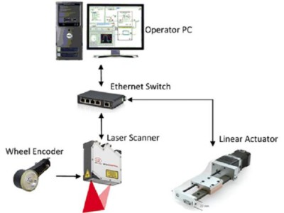
We used LabVIEW to develop the software running on the operator PC. The software uses various tools, which we explain later in this case study. It receives surface measurements from the laser scanner, buffers them, and performs analysis to determine further operation of the station. All components communicate with the PC through Ethernet.
Alternative Solutions
Prior to selecting LabVIEW as our software, we considered developing the solution in C as our third-party hardware could support both platforms. TBG Solutions has developed systems in both languages in the past, and we felt LabVIEW offered more benefits. We believed we could develop a better system in a shorter period of time, without sacrificing anything in return.
Implementation
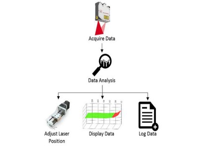
We designed the software to execute in a set sequence:
1) Data acquisition
2) Analysis
3) Additional parallel processes that act upon the results from the analysis stage
4) Linear actuator control, data display, and data logging
The start point of the looped execution sequence (Figure 4) is at data acquisition. We implemented the laser using LabVIEW’s built-in tool for third-party DLLs, which streamlined the driver development. The acquisition consisted of 640 points per measurement, giving a 150 mm wide surface map. Next, we buffered the measurements in the analysis stage, where we executed a series of algorithms to examine the measured surface. These involved identifying flares, identifying new steel strips and their deviation in width, and calculating the correct laser position to ensure uniform measurements. The results of these algorithms determined further operation of the parallel processes.
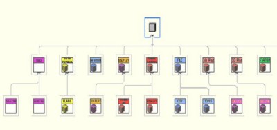
We implemented our design using the LabVIEW object-oriented programming (OOP) functionality, which was an ideal tool due to its ability to dynamically dispatch various instances of the same VIs and encapsulate data for each area of the execution sequence. Adding this to the other benefits, the graphical aspect of LabVIEW (Figure 5) delivered the perfect platform for a swift and understandable development of a hardware abstraction layer (HAL). This benefitted the development process in two major ways:
1) It accommodated a hardware-free development process as we could easily implement simulation classes, which prevented the development from being on hold when hardware was unavailable.
2) The modular nature of the implementation made the system more expandable as it accommodated for the event of exchanging hardware, analysis, or file types.
Another key LabVIEW feature that we used extensively during the development process was custom probing. We could view data in various formats, directly as the programming executed, which aided the development process as it made debugging significantly more straightforward.
Operator PC Interface
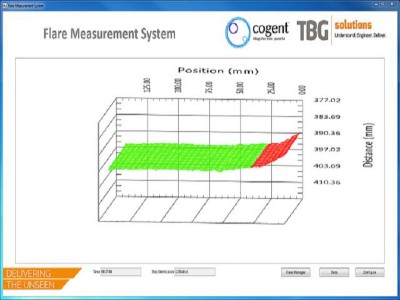
The 3D surface map is the core focus of the interface. The operator can use it to inspect the acquired data under any desired angle with accurate length and height measurements. We implemented the graph using the built-in 3D mesh function in LabVIEW. We found it easy to use, so we could quickly and simply implement the design.
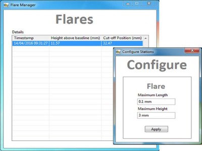
Identified flares are reported (Figure 7), and we can view their dimensions in a dedicated window to amplify the accuracy of removing the defect. We can configure the identification criteria to allow flexibility in the analysis process.
Conclusion
Using LabVIEW, we produced a professional application that met our objectives. The intuitive front panel components drove the quick and easy development of a complex UI that accommodated our underlying functional needs. Furthermore, the built-in tools and communication protocols sped up the process of developing the software infrastructure. This allowed us to focus on more complex areas of the system, which made the whole development more time and cost efficient. In addition, the previously explained benefits of OOP helped us adapt the solution for future opportunities that could involve the automation of the cutting-off defects.
The solution will benefit our client in more than one way as the vast amount of data acquisition will produce quality information available for reviewing. The customer can improve the quality of their steel and become increasingly more competitive in the British steel industry.
Overall, LabVIEW has again proven to be a great platform for developing a scalable and flexible solution. TBG Solutions will most certainly continue to use LabVIEW.
Author Information:
Marcin Polaszyk
TBG-SOLUTIONS
3A Midland Court, Barlborough Links
Chesterfield
United Kingdom
Tel: +44 (0) 1246 819 100
marcin.polaszyk@tbg-solutions.com, info@tbg-solutions.com
An NI Partner is a business entity independent from NI and has no agency or joint-venture relationship and does not form part of any business associations with NI.