Testing Rocket Propulsion Systems with NI VeriStand
John Bergmans, Co-Founder and President, ATRX, Inc.

Case Study Highlights
- VeriStand enabled ATRX to efficiently control propulsion tests, automating test phases from pre-test to post-test with real-time sequences and alarms.
ATRX customized their existing software for a new small thruster test stand in just two weeks, showcasing VeriStand’s adaptability and rapid development capabilities.
VeriStand’s user-friendly interface allowed customers to quickly modify test sequences and UI with minimal support, ensuring operational flexibility and ease of use.
“The expandability and ease-of-use of VeriStand have proven to be key benefits over multiple propulsion programs. Sophisticated test systems can be developed quickly using VeriStand, yet its intuitive design also allows new users to get fully up to speed on these systems within days!"
— John Bergmans, Co-Founder and President, ATRX, Inc.
The Challenge
ATRX needed to test a novel propulsion technology with a test system capable of configuring and operating real-time test applications. The test solution needed to be easy to use and have a short learning curve to facilitate fast test system completion and ensure high developer productivity while handling changing test requirements.
The Solution
VeriStand helped ATRX, Inc. overcome engineering challenges. The solution includes easy-to-configure user interfaces, a modular architecture for seamless integration between the UI, system configuration, and test logic, and compatibility with most NI real-time controllers. It also supports distributed systems and allows custom enhancements using NI LabVIEW, making it ideal for propulsion system testing.
Architecture
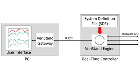
There are three key components of a VeriStand-based test software system:
- The VeriStand engine that processes data and accesses hardware I/O channels on a Linux real-time controller in the NI CompactRIO or PXI platforms
- The VeriStand gateway which acts as a central access point for all data in the system and typically runs on the operator’s PC
- The VeriStand UI that runs on the operator’s PC
Figure 1: Key Components of a VeriStand System
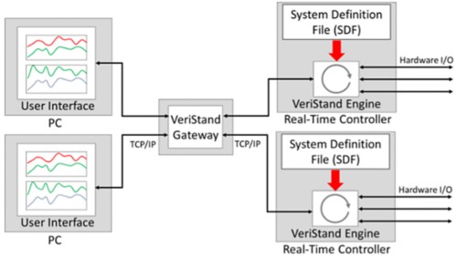
A notable feature of VeriStand is that it can easily accommodate expansion for multiple users and multiple real-time hardware platforms, as seen in Figure 2.
Figure 2: Distributed VeriStand System with Multiple Controllers and User Operator Stations
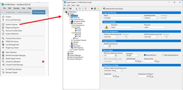
System Explorer and System Definition File
The low-level functionality of the VeriStand engine is determined by the system definition file (SDF). This file is deployed to the real-time controller(s) at the start of system operation.
The SDF, which is configured using the VeriStand System Explorer, describes functions such as alarms and simple automatic procedures, from which more complex responses such as red-line monitoring can be implemented. The SDF also defines other functions, such as data processing (e.g., low-pass filtering) and data logging. Mapping between channels is also set in the SDF.
Figure 3: VeriStand Project Window (left) and System Explorer Window (right)
Real-Time Sequences
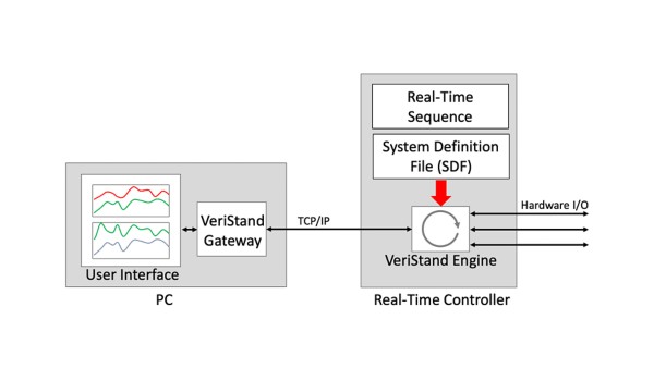
Real-time sequences are an additional layer of logic that define the behavior of the system when testing a propulsion system or any other unit under test (UUT). In the case of propulsion testing, a real-time sequence would define the logic to start, run, and shut down the propulsion system. The real-time sequence can also include abort logic to define the system response to off-nominal conditions.
Figure 4: Additional System Logic Can Be Added Using Real-Time Sequences
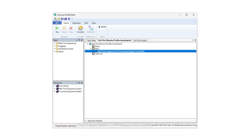
Real-time sequences are created and launched from the Stimulus Profile Editor.
Figure 5: Stimulus Profile Editor is Used to Create and Launch Real-Time Sequences
NI LabVIEW API
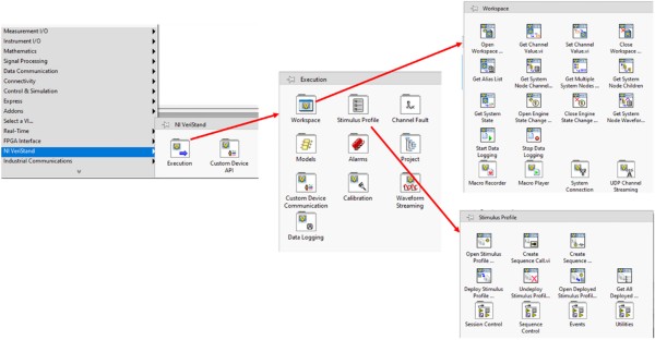
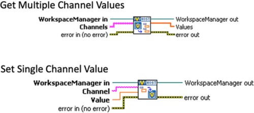
VeriStand includes a LabVIEW API that can be used to greatly expand the capabilities of a test system. When VeriStand is installed on a developer platform, a set of VIs are added to the LabVIEW tools palette that provide access to this API. VIs to read and write VeriStand channels are included in the API.
This API is useful for developing LabVIEW VIs with features that are not present or are difficult to implement in VeriStand, such as reading and writing configuration file data and controlling properties of UI elements.
Figure 6: LabVIEW API for VeriStand in Tools Palette
Figure 7: VIs to Read and Write VeriStand Channels in LabVIEW
Propulsion Testing Using VeriStand
Air Turbo Rocket Testing (ATRX)
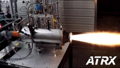
ATRX, Inc. of Huntsville, Alabama, is developing a unique propulsion system known as an Air Turbo Rocket which combines rocket motor and jet engine technologies. VeriStand is used to remotely control the test stand through all phases of an engine test. The phases are pre-test operation when the engine is prepared for firing, during hot fire testing when it is used for automatic engine control (Figure 8a), and finally during post-test operation to safe the engine and test stand. Automatic test control is implemented using a combination of VeriStand alarms, procedures and real-time sequences.
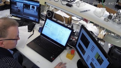
The ATR user interface (Figure 8b) consists of three screens. One screen includes a P&ID diagram representing the flow network of the stand. Boolean controls superimposed on the P&ID allow the user to toggle the valves and control other devices on the stand. Numeric controls on the P&ID display key instrumentation data such as pressures and temperatures. This screen is also used to launch real-time test sequences and features a software interlock for the sequencer function.
A second screen is used to configure hot fire test parameters, and a third screen shows real-time instrumentation data.
A CompactRIO cRIO-9030 controller and four cRIO I/O modules are at the core of the data acquisition system hardware for this test stand.
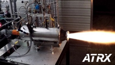 |  |
a) Air Turbo Rocket Hot Fire Test |
b) Operator Console |
Figure 8: Air Turbo Rocket Testing Using VeriStand
Small Thruster Test Stand
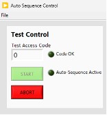
As an example of the productivity that can be achieved with VeriStand, ATRX was recently commissioned by a commercial NewSpace company to develop a turnkey test stand for testing small thrusters. Although this thruster and the propellant feed system of this stand were quite different from the Air Turbo Rocket system, by modifying the existing ATR test stand software, the software for this thruster test stand only required about two weeks to develop. One feature of this system that illustrates the use of the LabVIEW API is a stand-alone LabVIEW-based auto sequence control window (Figure 9). This window provides a software interlock that disables the hot fire auto-sequence START button until the operator enters a unique PIN code.
VeriStand’s expandability and ease of use were evident when our customer began using the system. Within days, they were up to speed on using the system and modifying the user interface to suit their needs. They were also able to modify the real-time hot fire sequence test requirements with little support from ATRX.
Figure 9: Software Interlock Implemented in LabVIEW
Other Systems
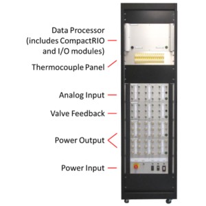
Bergmans Mechatronics, LLC (BML), a sister company of ATRX and an NI Partner, has used VeriStand for numerous additional propulsion testing systems. One notable BML project was to develop two rack-mount modular data acquisition and control systems (M-DACS) for propulsion testing (Figure 10) for a NewSpace customer. Both systems featured the use of VeriStand and CompactRIO hardware.
As with the ATRX small thruster test stand, BML’s customer quickly became familiar with VeriStand and required very little support to operate and modify these systems.
Figure 10: Modular Data Acquisition and Control System (M-DACS)
