The Benefits of Regenerative Loads & Sources: Removing the Cost of Heat
Overview
High-power testing environments and manufacturing require a steady flow of power from a facility connection. This flow is typically achieved with either a traditional air- or water-cooled load that converts power into waste heat. As a result, the facilities operate a chiller to remove the waste heat from the workspace, which incurs additional costs to operate the chiller appropriately.
Regenerative loads recycle the unit-under-test (UUT) output power and convert it into usable electricity, which can be redirected back onto the facility or the UUT. This feature makes the test system more energy-efficient, reduces the total power demand, and significantly decreases waste heat. For example, a regenerative load with over 90% efficiency can return more than 90% of the UUT's output power to the facility and convert less than 10% of the UUT power into heat. Thus, regenerative loads not only reduce electrical costs but also eliminate the need for expensive equipment required for facility cooling.
Contents
- Traditional Loads
- Electronic Loads
- Regenerative Electronic Loads
- Removing the Cost of Heat
- How Much Savings Can Be Achieved?
- Total Cost of Ownership
- AC & DC Regenerative Test Equipment by NI—Programmable Power
- Next Steps
Traditional Loads
An air- or water-cooled power resistor is the simplest form of load.
A resistor has a fixed loading profile that follows Ohm’s Law (I = V/R) 2 and converts 100% of the discharge power (P = V*I =V /R) directly into heat. The maximum power that can be loaded depends on the resistor’s rating.
Air-cooled resistors dissipate the heat into the air. Air conditioning or fans are then used to remove the generated heat from the working area. In air-conditioned laboratory settings, an air-cooled resistor can represent a very low-cost, flexible, and simple load. However, the amount of heat generated by air-cooled resistors makes it impractical for high-power testing or manufacturing environments.
Water-cooled resistors have an electrically isolated water connection, allowing water to carry the heat away from the device. Unfortunately, the water may contain additives or contaminants that can produce an electrical hazard if the resistor is damaged or if there is a leak to the connection. The requirement of a water connection limits where and when this type of device can be used.
Electronic Loads
An electronic load converts a hundred percent of the discharge power (P = V*I) directly into heat. Unlike resistors, electronic loads can provide more sophisticated loading profiles such as constant current, constant voltage, and constant power, in addition to constant resistance. Moreover, the load profile can be changed dynamically without the need to disconnect the UUT.
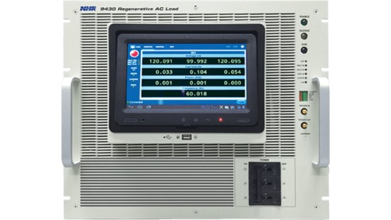
Figure 1: AC Electronic Load
Air-cooled electronic loads dissipate the waste heat into the air and can be used anywhere in a laboratory or manufacturing space, provided there is sufficient space or air-chiller capacity. Conversely, water-cooled electronic loads dissipate the waste heat through a water connection, which limits where these loads can be used. Additionally, testing can get interrupted when the water-chiller system is under maintenance.
Regenerative Electronic Loads
Regenerative electronic loads convert discharge power (P = V*I) back into usable electricity for the facility, thereby increasing flexibility in two ways.
First, the total power demand as well as the associated electrical cost is reduced.
Second, regeneration creates significantly less waste heat, which in turn reduces the energy and equipment required for facility cooling. This allows for maximum flexibility when planning, upgrading, or rearranging laboratory or manufacturing workspaces.
Removing the Cost of Heat
Consider the power flow associated with a traditional load as shown in Figure 2.
Figure 2: Power flow using a traditional load
Power is provided to the UUT from a facility connection. The output of the UUT is then loaded with a traditional load, which converts this power into waste heat. Then, additional power is required to operate a chiller in order to remove the waste heat from the workspace.
Assuming the UUT has a conversion efficiency of 90% and provides an output of 100 kW the UUT would contribute 11.1 kW of waste heat from conversion losses; the load converts the 100 kW output directly into waste heat. A total of 111.1 kW turns into 379,123 BTUs of heat, which will require significant additional power to remove this heat from the workspace.
Figure 3 shows this same test scenario when using a regenerative load.

Figure 3: Power flow using a regenerative load
Replacing a traditional load with a 92% efficient regenerative load reduces both utility usage and generated heat by >82%. The UUT will still generate 11.11 kW of waste heat from conversion losses. However, the regenerative load returns 92 kW of UUT’s output power to the facility and contributes only 8 W as waste heat. Total waste heat is reduced from 111.11 kW down to <30 kW or from 379,123 BTUs down to 65,206 BTUs, which lowers the amount of chiller power required to remove the waste heat from the workspace.
How Much Savings Can Be Achieved?
The UUT input power, Formula 1, depends on its conversion efficiency.
Formula 1: UUT Input Power = UTT Power/UTT Conversion Efficiency
The UUT will draw power from the utility and any regenerative sources. Therefore, the total utility power required (noted in Formula 2) will depend on the input power, amount of regenerated power, and power required to operate the chiller. Regeneration directly reduces the amount of input power required and will also reduce the amount of chiller power required.
Formula 2: Total Utility Power = (UUT Input Power − Regenerated Power) + Cℎiller Power
The amount of chiller power required in Formula 3 depends on how much power is converted to heat as well as the chiller type, size, and full/part loading energy efficiency ratios (EER). Industrial air-chillers at full load often reach an EER of 10 and similar water-chillers reach an EER of 20. Removing waste heat by an air-chiller requires approximately 34.12% more power, whereas a water-chiller requires approximately 17.06% more power.
Formula 3: Chiller Power Requirement
Note that in this simplified example, we are assuming a constant energy efficiency ratio for each chiller type. The actual, real-world energy efficiency can be affected by several factors including but not limited to maintenance, seasonal weather patterns, and loading amount.
In the table provided below, you can compare the costs of using a 92% efficient regenerative air-cooled load with the costs of using a standard air-cooled or water-cooled load. The table assumes a fixed electrical cost at $0.15/kWh. If the average electrical cost is known, the answer can be scaled to determine your operational costs.
| Load Type | Air Cooled Regenerative | Air Cooled Traditional | Water Cooled Traditional |
|---|---|---|---|
| Power into Unit under test | 111.1 kW | 111.1 kW | |
| Power at the load | 100 kW | 100 kW | |
| Power regenerated by the load | 92 kW | 0 kW | |
| Total waste heat generated | 19.1 kW | 111.1 kW | |
| Waste Heat (BTUs) | 65,206 BTUs | 379,123 BTUs | |
| Chiller Power required | 6.5 kW | 37.9 kW | 18.95 kW |
| Total Power Consumed | 25.6 kW | 149 kW | 130.05 kW |
| Electricity cost 0.15/kWh – Per Hour | $ 3.84 | $ 22.35 | $ 19.51 |
| Electricity cost 0.15/kWh – Per Day | $ 92.16 | $ 536.40 | $ 468.24 |
| Electricity cost 0.15/kWh – Per Year | $ 33,638 | $ 195,786 | $ 170,908 |
Table 1: Energy Costs Per Load Type
| Cost Savings for Each 10KW of Loading | Regeneration vs. Air-Cooled Load | Regeneration vs. Water-Cooled |
|---|---|---|
| 1 Year Savings | $ 162,148 | $ 137,270 |
| 5 Year Savings | $ 810,740 | $ 686,350 |
Table 2: Energy Costs Savings per 100 kW
Total Cost of Ownership
The total cost of ownership of traditional loads often includes far more than just the initial purchase of the load.
Traditional loads imply more electrical usage; higher electrical usage may require electrical system upgrades to support additional test stations. Each new station will generate a significant amount of waste heat, which may create the need for facility modifications such as new air handlers or water-chiller connection points. Furthermore, the chiller system may require upgrades and permits from the local government to handle the increased waste heat. All these costs and more can be associated with simple waste heat removal.
Regeneration, on the other hand, returns the power to the facility or UUT instead of converting the power to waste heat. Traditional air-cooled and water-cooled loads also have hidden operational costs when considering periodic maintenance cycles, annual inspections, and daily chiller record keeping. Additionally, the cooling systems may be unavailable when performing annual maintenance to keep them running at peak efficiency. Testing can be interrupted during this shutdown.
AC & DC Regenerative Test Equipment by NI—Programmable Power
NI offers regenerative loads specifically designed for DC as well as AC loading. Each load is modular, allowing for expansion or for use in parallel to meet future higher test-power needs. This modular-loading design allows maximum test flexibility and provides unmatched configuration options as well as future expandability.
The AC & DC regenerative loads include the NHR-9200 Mid-Voltage DC Battery Module Cycler and Emulator, the NHR-9300 High-Voltage DC Battery Module Cycler and Emulator with high-voltage DC loads, and the NHR-9430 Regenerative AC Load with four-quadrant AC loads. Additionally, the NHR-9410 Regenerative Grid Simulator System is a special bidirectional source that simulates the utility voltage and regenerates power sourced by grid-tied inverters.
Regenerative loads include an advanced built-in digital measurement system; voltage, current, power, and energy (Ah/kWh) measurements are immediately available. Additionally, all models include a waveform capture feature allowing a high-resolution capture of power related-events for detailed analysis.
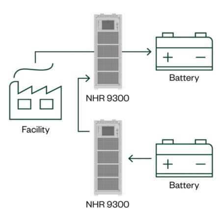
Figure 4: The NHR-9300 system requires less than 17 kW to charge and discharge two 100 kW batteries simultaneously.
Both AC and DC products are bidirectional, meaning that you can reverse the power flow using the same internal electronics. For instance, the NHR-9300 High-Voltage DC Battery Pack Cycler and Emulator can operate as a regenerative load or charging system. It can also emulate batteries for testing battery-related products. Additionally, the NHR-9430 Regenerative AC Load works as a true 4-quadrant AC load and can reverse power flow to emulate a solar inverter or energy storage system. Finally, multi-layered independent UTT safety features prevent damage, from environmental and operator error. When the safety limit is crossed, the test equipment shuts down and the UUT output is disconnected as a failsafe.
Energy savings through regeneration make higher power testing possible, unlike standard loads and power supplies. Consider the configuration consisting of two batteries shown in Figure 4: where one battery is discharged at 100 kW while charging the other battery at 100 kW. The total facility power required is less than 17 kW, making up only the losses and significantly less than the power required to charge a single battery.
There are a wide range of applications AC & DC regenerative test equipment and test systems are designed to support:
- Battery testing
- Chargers
- Electric vehicles (EV)
- Vehicle to grid (V2G)
- Flow batteries
- Fuel cells
- Microgrid testing
- Supercapacitors


