Advanced Features in PID Tuning
Overview
Please Note: The figures shown are simplified representations of block diagrams for conceptual purposes only.
Contents
- Classical Control
- Gain Scheduling
- Avoiding Integral Wind-up
- Non-SISO Systems
- Cascaded PID
- PID with Feed-forward Control
- Other Resources
Classical Control
Feedback control has been used since antiquity in the control of mechanical systems. Originally these systems utilized mechanical means, for example a float valve, to control temperatures, speeds and fluid levels. Modern computer-based control systems utilize feedback by taking a sensor measurement, comparing it to some desired setpoint and then adjusting a control output based on this difference. Controlling temperature, for example, can be done by measuring the current temperature, comparing it to the desired temperature value, and then using a heater or fan to move the temperature closer to the desired setpoint. The challenge then comes from figuring out how much to adjust control outputs to achieve the best response. Should the heater be turned on all the way or only part of the way? The basic PID controller compares a single input to a setpoint value and calculates a single output value to control the system, and the algorithm assumes that the response will be linear and not change over time. There are, however, certain techniques to apply the same PID algorithm to systems that don’t necessarily meet these criteria.
Gain Scheduling
One way that engineers have made use of PID in nonlinear systems is through the technique of gain scheduling. The most common reason people experience performance issues with PID control is the fact that incorrect gain parameters are chosen for P, I and D. In the case of nonlinear systems, optimal parameters might change, depending on what “state” the system is in. For example, many systems exhibit different characteristics during warm-up stages, than after they’ve been running for some time. Another example is using different gain parameters once a certain set-point has been reached, because the system responds differently once in steady-state. Gain scheduling is the process of modifying the gain parameters of P, I and D depending on the state of the system. These states can be defined by some time duration, or even by using system inputs. This method works best for systems that have predictable changes in dynamics, so that predetermined gains can be calculated and applied. Gain scheduling gives someone the ability to control a process with nonlinearities by dividing it up into sections that approximate linear characteristics. Each section can then be tuned to a different set of parameters that optimally control the system. Using the PID toolkit in LabVIEW, this is very easy to implement.
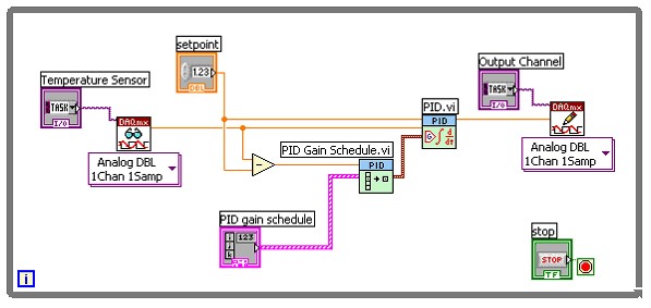
Figure 1: PID Gain Scheduling in LabVIEW
Figure 1 demonstrates the use of the PID Gain Schedule.vi to set PID gain parameters for the PID.vi based on the current difference between setpoint and measurement. In this example, a temperature sensor is being measured, and then compared to a user defined setpoint value. The difference between the two values, also known as the error term, is calculated and then sent to the gain scheduler. The scheduler itself is simply an array of PID gains that are indexed based on an input. As the temperature gets closer to the setpoint value, a different set of gain parameters can be used to achieve a better control response. There are many different ways to implement gain scheduling, and this particular way is good for reducing steady-state error by increasing the integral gain, or the I term, once your input has stabilized close to the setpoint.
Avoiding Integral Wind-up
The integral parameter of a PID controller continuously sums the error term of your system, which is very effective for reducing steady-state error. An unfortunate side-effect of constantly integrating this error is the possibility of “wind-up”. This is when accumulated error causes the measured signal to overshoot the desired setpoint based on the I term of the controller. This also introduces long delays and other destabilizing effects. Depending on the application, overshoot can be expensive and even dangerous due to loss of material or damage to surrounding hardware. Still, when trying to reach a particular set-point, the integral term makes overshoot almost inevitable. One technique to reduce the effects of integral wind-up is resetting the accumulated error once the system has started to stabilize near the setpoint. By resetting the PID function, you can still reap the benefits of reducing steady-state error with the integral term, but without causing a lot of overshoot. Here an example of how this could be implemented in LabVIEW.
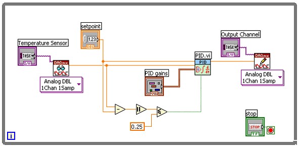
Figure 2: Avoiding integral wind-up by resetting PID.vi
Similar to the gain scheduling example, Figure 2 shows a temperature sensor being read, and then compared to a user-defined setpoint value. The error term is calculated and once it is within a certain value (in this case 0.25) the PID function is reset and then only steady-state error will be integrated from that point on.
Non-SISO Systems
While the PID algorithm is meant for single-input, single-output (SISO) systems, there are many ways to use this controller in multiple-input, multiple-output (MIMO) systems through software customization.
o Case structures for different outputs – positive and negative
o Parallel Loop PID
o Multiple PID
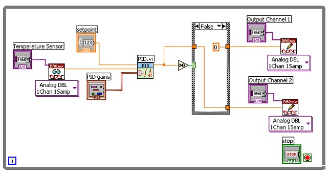
Figure 3: Single-Input, Multiple-Output (SIMO) Example
In Figure 3 there is a single input coming from a temperature sensor, but then two controller outputs, or actuators, being used to change the temperature. PID can output both positive and negative values, so this example uses a case structure to decide when each actuator will be used. Let’s say that output channel 1 is connected to a heater and output channel 2 connects to a fan for cooling the system. If the PID output value is positive, then we want to raise the temperature by writing the output value to the heater and turning the fan off by writing a zero to channel 2. However, if the PID output value is negative, the false case structure writes the output value to the fan, and a zero to output channel 1. This is a very common way of implementing PID with multiple outputs.
Cascaded PID
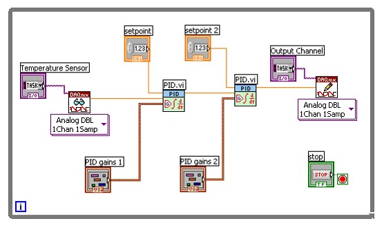
Figure 4: Cascaded PID Example
In this example we are sending the output of the first PID function into the input of the second PID function, therefore slowing down the response time and smoothening the output to the actuator. A more common way to implement cascaded PID is through the use of two inputs from the system, providing information about position and velocity for example. This multiple input, single output (MISO) system is very common for motion or position control application.
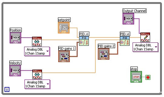
A position encoder is compared to the desired setpoint value, and then the calculated output becomes the setpoint for velocity control. This is particularly good when the system has inherent delays that are proportional to velocity. Friction, for example, will cause the system to lag, depending on the rate at which position is changing.
PID with Feed-forward Control
Disturbance decoupling is a variation on basic PID control that helps for systems that have a slow response to disturbances. If the disturbance can be measured, then the compensator output can be adjusted immediately to respond. For instance, if a fan introduces cold air into a temperature chamber, the heater output can be increased immediately rather than first waiting for the temperature to drop in the vicinity of the temperature sensor.
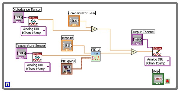
Figure 6: PID with Feed-Forward Control
In the figure above, a disturbance sensor is measured, multiplied by some user-defined gain value, and then added to the PID output value. If the disturbance increases, the compensator output channel will immediately increase to maintain control of the system. This approach is not always necessary since increasing the proportional gain on a traditional PID compensator will also improve disturbance rejection, and doesn’t require that the disturbance be measured.
Other Resources
• LabVIEW PID Control Toolset User Manual
• Point-by-Point Analysis User Manual
• Control System Design Guide, George Ellis, 2000, by Academic Press
Related Links:
The LabVIEW PID Toolkit is now included in the Full and Pro editions of LabVIEW