Under the Hood of NI ATE Core Configurations
Overview
Build an automated test system with core mechanical, power, and safety infrastructure offered by NI ATE Core Configurations. These systems provide the ultimate balance in standardized core components to simplify design and documentation, along with the layout flexibility for PXI, NI CompactDAQ, and other instrumentation.
The ATE Core Configurations can help you accelerate system design, reduce integration burden and risk, and shorten time to deployment for an automated test system. Every ATE Core Configurations rack includes integrated power distribution, cooling, and rack control units (RCUs). These systems have scalable mechanical and power profiles to cover applications ranging from basic validation bench design to high-power, high-reliability, globally deployed test stations.
- Rack Sizes
- 15U: designed for DUT-on-top or lower power systems
- 38U: just under 2m tall to fit through standard doors
- 44U: can support up to 7 PXI chassis
- Power Distribution
- AC and DC power options available
- Up to 36 kW of power
- Options for three-phase distribution within rack
Contents
- Mechanical Infrastructure
- Power Entry and Distribution
- Selecting the Appropriate ATE Core Configurations
- Next Steps
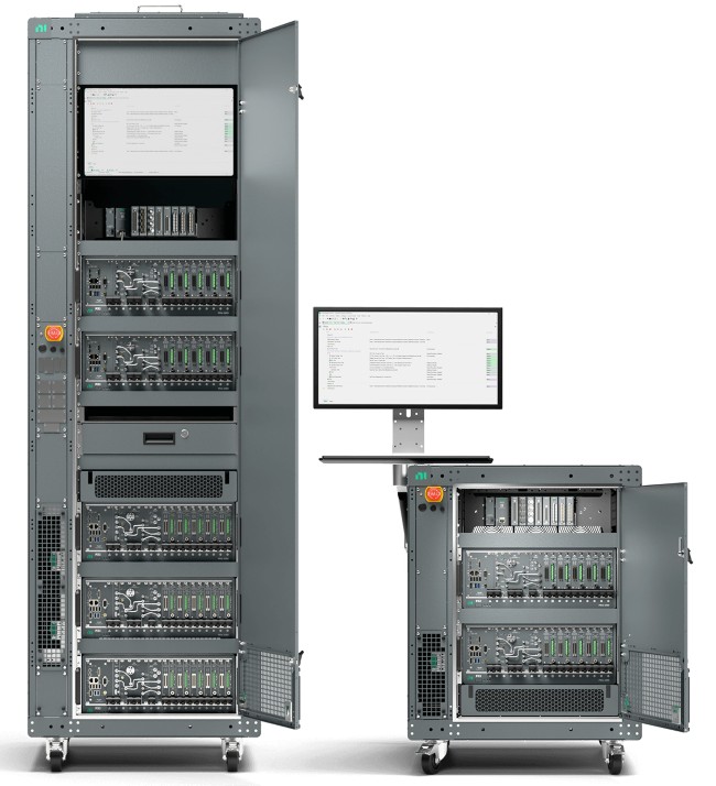
Figure 1: ATE Core Configurations provide the instrumentation, mechanical, safety, and power infrastructure needed to build a smarter automated test system.
Mechanical Infrastructure
ATE Core Configurations are based on the 19-inch rack that is designed for accessibility, simplicity, and global deployment. Table 1 outlines key specifications for each model.
| Model | Height (including casters) | Width | Depth | Max. Static Load | Caster Support |
|---|---|---|---|---|---|
| 15U | 31.148 in. (892.76 mm) | 26.5 in. (673.1 mm) | 33.46 in. (850 mm) | 1,200 lb. (544 kg) |
|
| 38U | 75.398 in. (1915.1 mm) | 26.5 in. (673.1 mm) | 33.46 in. (850 mm) | 1,200 lb. (544 kg) |
|
| 44U | 85.922 in. (2182.4 mm) | 26.5 in. (673.1 mm) | 33.46 in. (850 mm) | 1,200 lb. (544 kg) |
|
Table 1: Key Mechanical Specifications
Mounting Rails
Each ATE Core Configurations contain three sets of mounting rails (m6 or 10–32 threads) to easily mount equipment of different sizes and provide flexibility for thermal management. The total mounting depth is 31.5 in. (800 mm), the middle-mounting rail is optional, and location is reconfigurable.
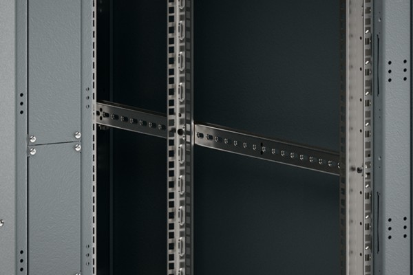
Figure 2: Removable side walls, accessible rear door, and hinged mounting panels make the ATE Core Configurations rack readily serviceable.
Serviceability
The racks have all power entry and distribution components mounted in a 2U-wide vertical space to the left when viewing the front of the rack. All equipment mounted in the side space is mounted on swinging panels for added serviceability. Doors and side panels are removable for easier access, with side panels having a trip to prevent them from being opened during use.
Airflow and Thermals
ATE Core Configurations include a highly serviceable top-fan kit containing six 4-inch fans. The fan speed can be controlled by the RCU. The speed is variable and can be set higher for greater internal thermal loads or lower to decrease noise in a moderate ambient environment. The fans are pre-wired to the power distribution unit.
The 38U and 44U racks intake air at the bottom rear of the rack through an air inlet at the bottom of the rear door and exhausts through the top of the rack. The 38U and 44U rack configurations can exhaust up to 11 kW. The 15U rack, designed for DUT on top use, intakes air at the bottom front of the rack and exhausts at the top of the rear of the rack to facilitate airflow through the rack. The 15U racks can handle up to 3.6 kW.
Safety Features
All ATE Core Configurations have several safety features, including convenient Emergency Power-Off buttons, tip safety, over temperature thermal protection, and more. All racks are certified IEC/EN 61010-1 compliant. Find out about component level safety features in the User Manual.
Emergency Power-Off (EMO)
The EMO push button is used to shut down the system in the event that there is danger to the operator or device under test. The EMO switch is prewired to the power entry panel (PEP) and, when the EMO button is pressed, switches within the PEP disconnect power to the AC and DC PDUs. The RCU remains powered on to maintain communication for health monitoring and logging information.
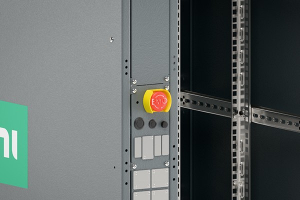
Figure 3: Emergency Power-Off (EMO)
Tip Safety
Every system is completely customizable in terms of the instrumentation and accessories necessary to meet the requirements of an application. Therefore, it can be difficult to ensure the layout of the system will be balanced or stable when transporting throughout the factory floor. All ATE Core Configurations are evaluated based on the final, custom configuration, and steel ballasts are appropriately added to the base of the rack (below usable mounting space) to ensure the system is stable and meets IEC/EN 61010 tip and pull tests.
Rack Control Unit
Every ATE Core Configurations rack contains a rack control unit (RCU), which comes with a C# API supported on Windows 10. The RCU can be used for uptime, monitoring, and reporting activities. It also enables critical control features such as startup and shutdown sequences.
Key Features and Capabilities:
- Monitor system state and health
- Control startup and shutdown sequence, including soft shutdown report
- Aware of system population and power set
- Monitor input power and power distribution
- Control and monitor fan speed and PWM (predict aging)
- Monitor safety thermal shutdown
- Monitor and report ITA pin status
- Communication path for Interface devices (DUT fixture, calibration device, continuity checker)
- Local system storage
- Enables test cell features (tower light, pneumatics)
- Built-in 4 port USB hub
- Reporting for information/data collected by RCU
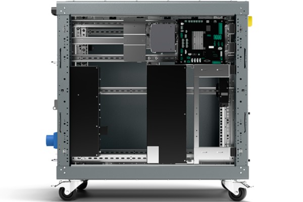
Figure 4: 15U ATE Core Configuration with Rack Mount Control Unit mounted in the top right corner, the RCU is included in every size of ATE Core Configurations
Configurable I/O
All racks have configurable front and rear I/O panels. At a minimum, this includes an emergency power-off (EMO) button, rack power button, and status indicator on the front panel with an Ethernet port on the rear panel. The I/O panels can also contain rear system circuit breaker, rear EMO, front Ethernet, IEC 60309 power input connector, hardwired connection for high current systems, integrated 4-port USB 2.0 hub, and external C13 power with GFCI. This can also include upgrades for standard test needs such as GPIB, RS232, pneumatics, and other upgrades.
Power Entry and Distribution
RMX Power Entry Panels
ATE Core Configurations include a PEP mounted in the side space, designed to maintain clear separation of internal cabling from operator-accessible connections to provide better security and serviceability. Each rack contains a vertical grounding bus bar that extends from the top to bottom of the rack for grounding all internal equipment within the rack. This bus bar is connected to the main ground inlet on the power entry panel. The power entry panel also contains circuit protection, transient suppression, and EMI filtering to mitigate RF noise on the incoming power line.
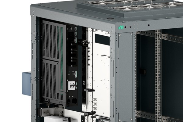
Figure 5: PEPs increase the safety and serviceability of ATE core configurations.
There are six versions of the PEP, depending on the system power:
| Selection Guide | Power | Phase | Current Rating | Branch Rating | Voltage Rating | Input Connection | Name | Compatible Rack Sizes |
|---|---|---|---|---|---|---|---|---|
Low Power | 3.8 kW | 1ϕ | 16 A | 20 A | 100–240 V | IEC 60309 | RMX-10140-16S2 | 15U only |
| Mid Power | 5.7 kW | 1ϕ | 24 A | 30 A | 100–240 V | IEC 60309 | RMX-10140-24S2 | 15U, 38U, and 44U |
| High Power Wye | 11.5 kW | 3ϕ Y | 16 A | 20 A | 100–240 V | IEC 60309 | RMX-10140-16Y2 | 38U and 44U |
| High Power Delta | 13.3 kW | 3ϕ Δ | 32 A | 40 A | 200–240 V | Hardwire | RMX-10140-32D2 | 38U and 44U |
Ultra-High Power (3ϕ output) | 21 kW | 3ϕ Δ | 50 A | 63 A | 200–240 V | Hardwire | RMX-10140-50D2P | 38U only |
| Ultra-High Power (3ϕ output) | 36 kW | 3ϕ Y | 50 A | 63 A | 200–240 V | Hardwire | RMX-10140-50Y2P | 38U only |
Table 2: Six PEP Versions Specifications
Single-Phase Power Distribution Unit
ATE Core Configurations with single phase power entry panels contain one or two single-phase PDUs that support global input voltages (100–240 V, 50–60 Hz). These are cabled directly to the power entry panel. The 16 A PEP version is only supported for 15U racks and comes with a single PDU. The 24 A PEP version comes with two PDUs. DC rails for 12, 24, 28, and 48 V are also provided.
Key Features:
- Eight IEC C13 outlets
- Two power sequenced outlet banks
- Circuit protection
- Remote inhibit and EMO
Three-Phase Power Distribution Unit
ATE Core Configurations with three-phase power entry panels can contain three of the single-phase PDUs. All units connect directly to the power entry panel for optimal power management. The Ultra-High Power PEPs listed in Table 2 have the possibility of distributing three-phase power within the rack. DC rails for 12, 24, 28, and 48 V are also provided.
Note: Further details of the single-phase and three-phase PDUs are in their specific data sheets.
Key Features:
- (6) IEC C13 Outlets
- (3) IEC C19 Outlets
- (4) DC Outlets: 12 V, 24 V, 24 V, 48 V
- (2) Power Sequenced Outlet Banks
- Circuit Protection (Master and Per Phase)
- Remote Inhibit and EPO
Note: Further details of the single-phase and three-phase PDUs are in their specific data sheets.
Selecting the Appropriate ATE Core Configurations
- How much space is required for equipment? 15U, 38U, or 44U
- a. Will the system need to fit through standard doors? 15U or 38U
- b. Do I want DUT on top capability? 15U
- How much power/current is required for equipment? Multiple options between 16 A (up to 3.8 kW) and 50 A (up to 36 kW)
- a. How many AC PDUs do I need? (see single and three-phase power distribution sections)
- b. Do I need three-phase distribution inside the rack?
- Where is the system being deployed? (120 V, 220 V, or 240 V environments)
- a. If facility power is three-phase, do I need a wye or delta input?
Next Steps
- Review the ATE Core Configurations Generation 2 User Manual
- Download the user manual to discover the first generation of NI ATE Core Configurations (24U or 40U)
- Contact an NI engineer to discuss your needs, configure your system, and get a quote
- Download the Fundamentals of Building a Test System white paper series
- Get a turnkey solution or consultation on your system architecture from more than 1,000 NI Partners worldwide
An NI Partner is a business entity independent from NI and has no agency or joint-venture relationship and does not form part of any business associations with NI.
