The PXIe-517x Family: The First Oscilloscopes with LabVIEW-Programmable FPGAs
Overview
The first oscilloscopes to include FPGAs that could be targeted and reprogrammed with the LabVIEW FPGA Module were the PXIe-5170R, PXIe-5171R, and PXIe-5172. With this leap forward in instrumentation technology, you can define the operation of your oscilloscopes to meet your needs now and in the future as your devices and experiments change. PXIe-517x oscilloscopes give you excellent channel density, accuracy, and measurement flexibility along with a user-programmable FPGA. Decrease your cost of test, shorten your time to market, and improve your test yield with the PXIe-517x reconfigurable oscilloscopes.
Contents
- The PXIe-517x Oscilloscopes
- High-Density, High-Performance, Simultaneously-Sampled Channels
- Software-Designed Instrumentation Versus Traditional Instruments
- High-Density Probing with PXIe-5172
- Key Application Areas
- Next Steps
The PXIe-517x Oscilloscopes
The PXIe-5170R, PXIe-5171R, and PXIe-5172 are ideal oscilloscopes for tackling measurement challenges that require many oscilloscope channels, the high measurement resolution of a 14-bit analog-to-digital converter (ADC), and the flexibility of programming the instrument with a standard device driver or customizing the device firmware with a user-programmable FPGA. The technology includes:
- Four or eight 250 MS/s simultaneously-sampled input channels
- 14 bits of measurement resolution with up to 11 bits of ENOB
- 100 or 250 MHz of analog bandwidth with up to 0.5 dB flatness
- A user-programmable Xilinx Kintex-7 FPGA that enables streaming rates of up to 3.2 GB/s
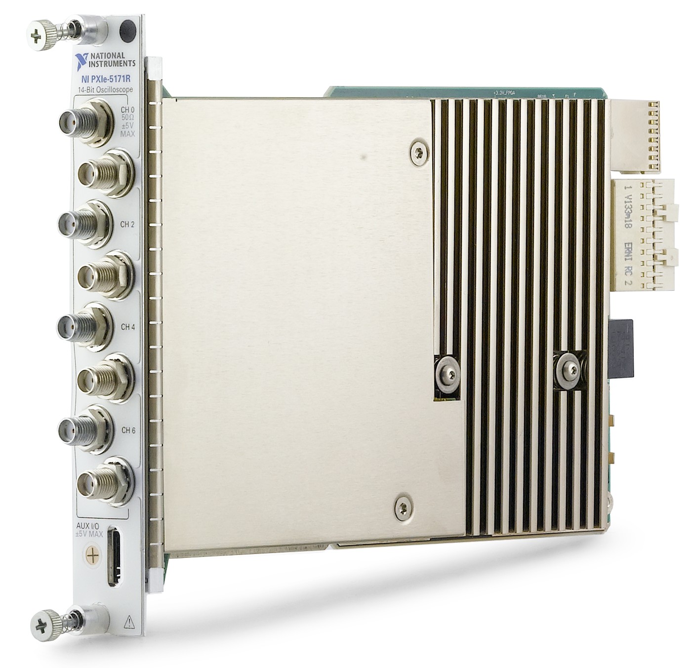
Figure 1: The PXIe-517x oscilloscopes are high-density, 250 MS/s reconfigurable oscilloscopes that are ideal for scientific research, high-performance machines, aerospace/defense test, and semiconductor.
This series of oscilloscopes shares a high-performance digital subsystem for data streaming and deep memory for long record storage as well as a common analog architecture that are brought together using a Xilinx Kintex-7 FPGA.
| Specification | PXIe-5170R | PXIe-5171R | PXIe-5172 | |||
| Resolution | 14 bits | |||||
| Sample Rate | 250 MS/s | |||||
| Input Range | 200 mVpp, 400 mVpp, 1 Vpp, 2 Vpp, 5 Vpp | 200 mVpp, 700 mVpp, 1.4 Vpp, 5 Vpp, 10 Vpp, 40 Vpp, 80 Vpp | ||||
| Offset | None | ±20 V | ||||
| Input Impedance | 50 Ω | 50 Ω and 1 MΩ | ||||
| Open FPGA | Xilinx Kintex-7 325T | Xilinx Kintex-7 410T | Xilinx Kintex-7 325T | Xilinx Kintex-7 410T | ||
| Memory | 750 MB | 1.5 GB | 1.5 GB | 750 MB | 1.5 GB | 1.5 GB |
| Channel Count | 4 | 8 | 8 | 4 | 8 | 8 |
| Full Bandwidth | 100 MHz | 250 MHz | 100 MHz | |||
| Selectable Filters | None | 100 MHz | 20 MHz | |||
| Coupling Options | AC and DC | |||||
| Analog performance | ~ -78dBc (30MHz signal, anti-alias filter enabled) | ~ -80dBc (30MHz signal) | ||||
| >10.2 ENOB (full bandwidth, 0.4 Vpp – 5 Vpp ranges) | 11 ENOB (full bandwdith) | |||||
| 11 ENOB (anti-alias filter enabled, 0.4 Vpp – 5 Vpp ranges) | 11.9 ENOB (20 MHz filter enabled) | |||||
| Bus Interface | x8 Gen 2 PXI Express Link, sustainable streaming rates of 3.2 GB/s | |||||
Table 1: The PXIe-517x series of oscilloscopes has the right features and options to address your application.
Several PXI oscilloscopes are also available in the PXI Oscilloscope Bundle, which includes the oscilloscope and four slots for synchronizing different instruments.
High-Density, High-Performance, Simultaneously-Sampled Channels
To enable their compact, flexible, and powerful design, PXIe-517x oscilloscopes take advantage of technological advances, including low-power, high-resolution ADCs that use JESD204B high-speed serial interface for data transfer and high-performance, low-power Xilinx Kintex-7 FPGAs.
Low Power. High Performance.
PXIe-517x oscilloscopes use a low-power 14-bit ADC from Analog Devices that has excellent noise density. Using this ADC, NI engineers can include eight channels of 250 MS/s with very low noise into a single-slot PXI oscilloscope. The ADCs are not the only component that makes the PXIe-517x oscilloscopes possible. FPGAs continue to progress in number of logic cells, digital signal processing (DSP) slices, and I/O like multi-gigabit transceivers at an exponential rate while also decreasing the power required to use these features. Kintex-7 FPGAs from Xilinx provide the necessary processing power at the right power consumption to design the firmware of these reconfigurable oscilloscopes, whether that be the standard oscilloscope firmware from NI or your custom firmware designed with the LabVIEW FPGA Module.
High-Speed Serial Data Transfer
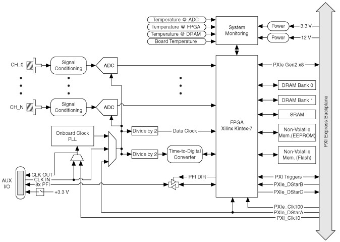
Power usage was not the only challenge in designing these oscilloscopes. Eight ADCs collecting 250 MS/s of 14-bit analog data create an enormous amount of data—approximately 4 GB/s. Transmitting that much data with a traditional ADC that communicates over many parallel digital lanes would be incredibly resource intensive. The ADCs on PXIe-517x oscilloscopes use a high-speed serial physical layer and protocol specific to data converters called JESD204. Using JESD204B, these ADCs can transfer many gigabits per second (Gb/s) of data to the Kintex-7 FPGA on the instrument.
Getting the analog data from the ADCs to the FPGA is only half the task. In many test applications, you must stream data from the oscilloscope to a host controller, peer data processor, or data storage. The PXIe-517x oscilloscopes use the Kintex-7 FPGA to stream data along the PCI Express backplane of the PXI Express chassis at up to 2.3 GB/s.
Figure 2: The PXIe-517x oscilloscopes are built around a 14-bit, Analog Devices ADC and a Xilinx Kintex-7 FPGA.
Software-Designed Instrumentation Versus Traditional Instruments
User-programmable FPGAs in your measurement system hardware provide benefits that range from low-latency device under test (DUT) control to CPU load reduction. The following sections describe various usage scenarios in more detail.
Improve Test System Integration With Onboard Decision Making
In many test systems, you must control the DUT or chip under test through digital signals. Traditional automated test systems can sequence through DUT modes and take the needed measurements in each stage. In some cases, automated test equipment (ATE) systems incorporate intelligence to progress between DUT settings according to the measurement values received.
In either scenario, software-designed instruments that incorporate a user-programmable FPGA result in cost and time savings. Consolidating measurement processing and digital control into a single instrument reduces the need for additional digital I/O in the system and avoids configuring triggering between instruments. In cases where the DUT must be controlled in response to measurement data received, software-designed instrumentation closes the loop in hardware and reduces the need for decision making in software at a significantly higher latency.
Decrease Test Time and Increase Confidence With In-Hardware Measurements
Today’s software-based test systems can perform a limited number of measurements in parallel, but software-designed instrumentation is limited only by the available FPGA logic. You can process dozens of measurements or data channels with true hardware parallelism, removing the need to choose between measurements of interest. With software-designed instruments, functionality such as real-time spectral masking is achieved with dramatically higher performance and at a fraction of the cost compared to traditional boxed instruments.
The low latency associated with performing measurements in software-designed instruments means that you can take tens or hundreds of live measurements and average them together in the same amount of time as a traditional test system requires to take a single measurement. This results in improved test-result quality and increased confidence in your measurements.
Focus Only on Interesting Data With Custom-Defined Triggers
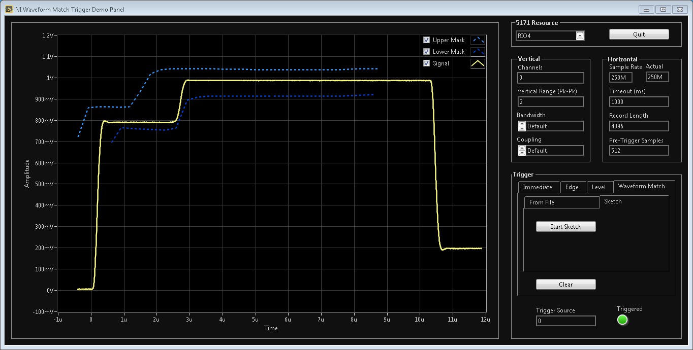
Traditional instrument options for low-latency trigger behavior are fixed according to the hardware being used, but with software-designed instrumentation you can incorporate custom triggering functionality into your device to quickly zero in on situations of interest. Flexible hardware-based triggering means that you can implement custom spectral masks or other complex conditions as criteria for either capturing important measurement data or activating additional instrumentation equipment. See a custom trigger built with LabVIEW and implemented on a software-designed oscilloscope in this 5-minute webcast.
Figure 3: NI’s instruments with programmable FPGAs help you to create custom measurement features like triggers and signal processing as well as interoperative device firmware.
Reduce CPU Processing Loads With Real-Time Onboard Signal Processing
Processing large amounts of data can tax even the most capable commercial CPUs, resulting in systems with multiple processors or extended test times. With software-designed instrumentation, you can preprocess data in hardware, potentially reducing the CPU load significantly. Computations such as fast Fourier transforms (FFTs), filtering, digital downconversion, and channelization are implemented in hardware, reducing the amount of data passed to and processed by the CPU.
Gain Confidence in Final Design Performance With Rapid Prototyping
You traditionally use instrumentation just for test and measurement applications, but the connectivity between I/O and software in modular instruments gives you the ability to prototype electronic systems using instrumentation. For example, you can prototype advanced radar systems using digitizers and RF signal analyzers; the connectivity to a user-programmable FPGA allows quicker advanced algorithm deployment in prototype and faster proof-of-concept validation.
High-Density Probing with PXIe-5172
NI has introduced numerous oscilloscope probes for high-voltage, high-bandwidth, and low-level signals. The PXIe-5172 has high-density SMB connectors but is capable of interfacing to many of these probes. To use probes with the PXIe-5172, NI recommends using a cable adaptor (NI part number 781449-01 for one adaptor, or NI part number 781449-10 for ten adaptors). With an adaptor, you can use the following probes:
Passive Probes
Passive probes are very flexible and can measure signals up to 500 MHz or 300 Volts. The PXIe-5172 is compatible with the following NI passive probes.
- CP500X—500 MHz, 1.2 m, 10X Cable Divider Probe
- CP400X—400 MHz, 2 m, 10X Cable Divider Probe
- SP500X—500 MHz, 10x Passive Probe
- SP500C—500 MHz, 100x Passive Probe
Active Probes
Active probes are used for more specific signals like high-bandwidth, high-voltage, or current signals. The PXIe-5172 is compatible with the following NI active probes:
- NI 5191—800 MHz, Differential Active Probe
- SA1000X—1 GHz Single-Ended Active Probe
- SA1500X—1.5 GHz Single-Ended Active Probe
- SA2500X—2.5 GHz Single-Ended Active Probe
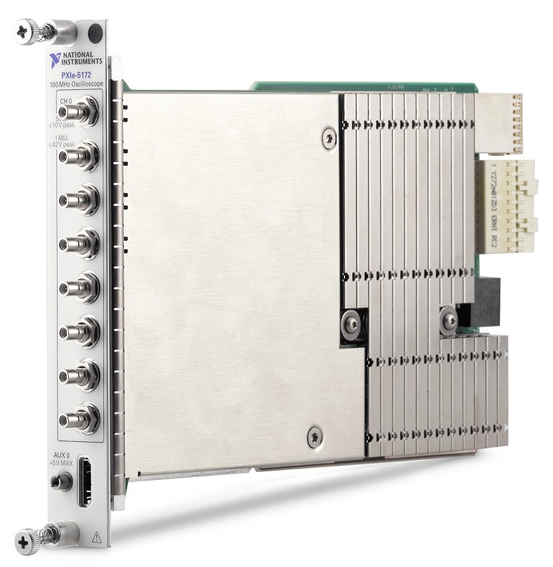
Figure 4: The PXIe-5172 is a highly flexible 8-channel oscilloscope capable of sampling on external clocks and accepting 80 Vpp signals.
Key Application Areas
Scientific and Academic Research, High-Performance A/D Systems (RADAR, Mas Spectrometry, etc.)
Instrument performance and flexibility are the most important features in science applications such as high-energy physics. Most of the signal processing and control tasks for these applications traditionally used analog electronics and relatively slow ADCs to capture preconditioned signals. Today, with fast high-resolution ADCs (14 bit and 250 MS/s and above) you can sample signals directly from sensors. Using instruments with user-programmable FPGAs, you can perform signal processing in real time during acquisition instead of in postprocessing on a PC. You get faster results and more flexible, efficient control in scientific experiments.
Efficient Real-Time Feedback With Inline Processing
Many science experiments rely on control systems that keep the setup in a well-defined state. For example, in fusion research systems like the DIII-D tokamak, the plasma is heated with RF power, which requires you to measure complex RF reflection coefficients and derive appropriate control parameters from the measurements.
Learn more about fast RF power diagnostics using FlexRIO and a user-programmable FPGA.
In particle accelerators and synchrotron machines, you have to monitor particle beams’ trajectories constantly to keep them on track with magnets that require the correct control input. Oscilloscopes with user-programmable FPGAs can help to solve applications like the DIII-D tokamak, because their fast and inherent parallel processing allows analysis of a signal and frequency domain at the same time, as well as very fast control loops. You can customize the FPGA to also monitor safety critical parameters to trigger a shutdown in case the system enters an unwanted state.
Using the high-speed PXI Express bus, you can pair oscilloscopes with output modules that generate control signals for experiments or stream data continuously to a storage medium at speeds of more than 3 GB/s per instrument. Another benefit of user-programmable FPGAs is you can change the explained processing and control algorithm very quickly. You can load an already compiled bit stream into the FPGA in fractions of a second to alter the oscilloscope’s behavior.
Faster Discoveries With Real-Time Event Detection and Data Reduction
It is often challenging to identify events of interest. Typically, you can look for events during post-processing after the actual data acquisition is complete, but this method takes more time and requires you to store large amounts of data.
For a more efficient way, reduce data to a minimum by deciding right at acquisition time which signals to keep and which to discard. Often the only parameters of interest are timestamps and calculated energy pulses, so returning these parameters from an instrument is more efficient storage-wise and enables longer measurements because the already extracted results can be easily offloaded to the host PC.
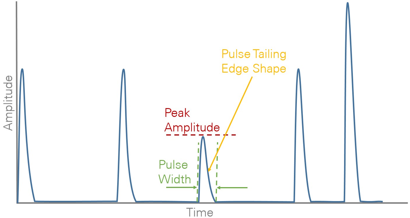
For example, time-of-flight applications chart particles and energies over time. In the Figure 4 diagram, faster particles are shown on the left (short flight times) and slower particles on the right.
Figure 5: The PXIe-5170 and PXIe-5171 are ideal for applications that include time-of-flight calculations or real-time pulse processing to collect required data.
The measurement system’s tasks are to extract, time stamp, and measure the energy pulses and eliminate the time (acquired data) without pulses in between, often called zero-suppression. This is easy to implement in an FPGA because every sample can be evaluated in real time. The general architecture for detecting events as shown in Figure 4 would be a pulse—such as a threshold—detector, followed by algorithms that fit a reference pulse—such as a Gaussian shape—on the detected pulse for estimating the maximum value. After detecting and storing the peak and the corresponding timestamp, you can either discard the acquired pulse or send it to another buffer for further analysis or display on the PC.
LabVIEW FPGA provides users with the tools to implement the necessary signal processing steps on oscilloscopes to filter and shape pulses, count and time stamp their occurrences, measure height and rise time, reconstruct baselines directly inside the instrument, and return the compressed results to a PC to make researchers more efficient in their work.
Aerospace and Defense Test
The lifespan of many aerospace and defense testers can reach 40 years and beyond. The challenges of replacing an obsolete instrument and recertifying a tester can be extremely costly. The reconfigurable nature of the PXIe-517x oscilloscopes makes them a good choice for new designs as well as drop-in replacements for obsolete instruments. Because many specifications or characteristics, such as triggers or filters, need to stay consistent through the generations of testers, these oscilloscopes help to alleviate backward compatibility issues that may arise by allowing you to reuse the hardware IP created in LabVIEW, helping to reduce both certification and maintenance costs.
See where NI is making an impact in the aerospace and defense industries.
Semiconductor Test
Testing the new semiconductor devices that are making modern wireless revolution possible requires high resolution, speed, and flexible instrument performance. The channel density, high resolution, superb spectral performance, and user-programmable FPGA of the PXIe-517x oscilloscopes make them ideal tools for making many of the fast analog measurements needed in semiconductor characterization and production test systems.
To learn more about NI's offering for semiconductor test, visit ni.com/semiconductor.
Next Steps
- Explore PXI Oscilloscopes and see how they outperform traditional box scopes
- Configure your PXI test system with the PXI Advisor
