How Is Temperature Affecting Your Strain Measurement Accuracy?
Overview
Contents
- Strain Gage Measurements
- Compensating for Temperature Drift of the Sensor
- Prevent Errors Caused by Lead Resistances
- Minimize Temperature Effects with Half-Bridge and Full-Bridge Sensors
- Gage Excitation and Self-Heating
- Summary
Strain Gage Measurements
The most widely used gage is the bonded metallic strain gage. The metallic strain gage consists of a very fine wire or, more commonly, metallic foil arranged in a grid pattern. The grid pattern maximizes the amount of metallic wire or foil subject to strain in the parallel direction. The cross sectional area of the grid is minimized to reduce the effect of shear strain and Poisson strain. The grid is bonded to a thin backing, called the carrier, which is attached directly to the test specimen. Therefore, the strain experienced by the test specimen is transferred directly to the strain gage, which responds with a linear change in electrical resistance. Strain gages are available commercially with the most common nominal resistance values of 120 Ω, 350 Ω, and 1,000 Ω.
In practice, the strain measurements rarely involve quantities larger than a few millistrain. Therefore, to measure the strain requires accurate measurement of very small changes in resistance. The gage factor is a strain gage's sensitivity to strain, expressed quantitatively as ratio of fractional change in electrical resistance to the fractional change in length. For example, suppose a test specimen undergoes a substantial strain of 500 me (microstrain). A strain gage with a gage factor of 2 exhibits a change in electrical resistance of only 2*(500*10-6 ) = 0.1%. For a 120 Ω gage, this is a change of only 0.12 Ω. To measure such small changes in resistance, and compensate for the temperature sensitivity, strain gages are almost always used in a bridge configuration with a voltage or current excitation source.
The general Wheatstone bridge circuit, illustrated below, consists of four resistive arms with an excitation voltage, VEX, that is applied across the bridge. The output voltage of the bridge, VO, is equal to:

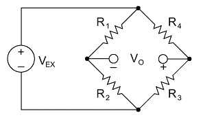
Figure 1. Wheatstone Bridge Circuit
From this equation, it is apparent that when R1 /R2 = R4 /R3, the voltage output VO is zero. Under these conditions, the bridge is said to be balanced. Any change in resistance in any arm of the bridge results in a nonzero output voltage. Therefore, if we replace R4 in Figure 1 with an active strain gage, any changes in the strain gage resistance unbalance the bridge and produce a nonzero output voltage that is a function of strain.
Compensating for Temperature Drift of the Sensor
Strain gage manufacturers attempt to minimize sensitivity to temperature by processing the gage material to compensate for the thermal expansion of the specimen material for which the gage is intended. While compensated gages reduce the thermal sensitivity, they do not totally remove it. A residual error on the order of 10 me/°C is still possible when you use a temperature compensating gage. Therefore, additional temperature compensation is sometimes necessary.
Further correction is possible by measuring temperature and using a correction curve to correct the data. Manufacturers print the polynomial coefficients of this curve to fourth order on each package of gages (see Figure 2 below). With the coefficients you can conduct temperature correction in software. An error as small as 1 me/°C is possible using this technique.
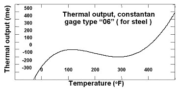
Figure 2. Thermal Output Rating
Prevent Errors Caused by Lead Resistances
Lead wire resistances also vary with temperature, and can have a great effect on the accuracy of strain gage measurements. Even if you have initially balanced the system, changes in the lead wire resistance with temperature can still introduce large errors in static measurements. This can occur even though the lead wire resistance is much smaller than the bridge resistance, which is not surprising considering that the temperature coefficient of copper is typically two orders of magnitude greater than the temperature coefficient of the gages.
Although you could connect to the gage with two wires in a quarter bridge circuit, drift caused by lead wire temperature change would be enormous. For this reason, you always perform static measurements using the three-wire circuit, shown here in Figure 3. The bridge remains balanced as long as lead wire resistances RL track with temperature.
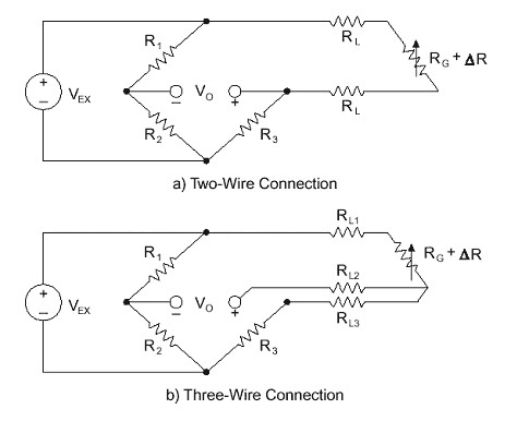
Figure 3. Two-Wire and Three-Wire Connections for Quarter-Bridge Sensors
Minimize Temperature Effects with Half-Bridge and Full-Bridge Sensors
By using two or four strain gages in a Wheatstone bridge, you can minimize the effect of temperature. These are called half-bridge and full-bridge configurations, respectively. See Figures 4 and 5. With all strain gages in a bridge at the same temperature and mounted on the same material, any changes in temperature affect all gages in the same way. Because the temperature changes are identical in the gages, the ratio of their resistance does not change, and the output voltage of the gage does not change. The simplest way you can correct for temperature drift is by using half-bridge or full-bridge configurations.
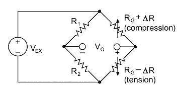
Figure 4. Half-Bridge Configuration
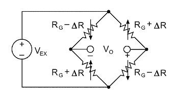
Figure 5. Full-Bridge Configuration
Gage Excitation and Self-Heating
The change in output voltage for a given level of strain increases in direct proportion to the excitation voltage. Increasing excitation voltage thus improves signal to noise ratio, but a practical limit is reached when the ill effects of gage self-heating become predominant. For steel, we recommend an excitation level between 2 to 5 watts/in2 . An optimum excitation voltage is best determined by an experimental procedure. With no load applied, you should examine the zero point of the channel while excitation level is progressively raised. Once instability in the zero reading is observed, you should lower the excitation until stability returns. It is best to perform this experiment at the highest temperature over which you are taking measurements. Obviously, using larger gages and higher resistance gages -- 350 instead of 120 ohms -- decreases the power per unit area dissipated, and higher excitation voltage is possible.
Summary
Temperature-related effects are one of the most common causes of measurement error with strain gages. By choosing the appropriate sensor for the application (compensated quarter-, half-, or full-bridge) and using the proper measurement techniques (wiring, excitation, and software linearization) you can minimize temperature drift effects and achieve the accuracy required for your application.