Glossary for RF Common Terminology
Contents
Overview
This article briefly defines common RF terms used when discussing RF applications or purchasing an RF module. These terms apply to many NI RF products and the industries and application in which they are used.
Glossary Definitions
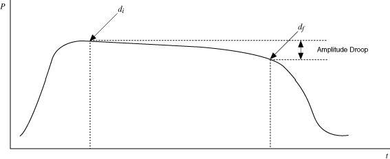
Amplitude Droop
Amplitude droop, measured in dB, is a measure of the amount that the signal power falls from the start of a specified measurement window (di) to the end of that window (df).Units: dB
Amplitude Modulation (AM)
Amplitude modulation (AM) is an analog modulation technique where the carrier signal amplitude is altered by a message signal. AM effectively generates two symmetrical side bands, and suppresses the carrier.
The fundamental equation for sine wave amplitude modulation is:
Amplitude-Shift Keying (ASK)
Amplitude-Shift Keying (ASK) refers to a type of digital modulation which assigns bit values (high/low) to discrete amplitude levels of an analog wave. ASK is achieved by modulating a carrier sine wave with a digital bit stream which results in a modulated carrier that is able to transmit digital data via variations of its amplitude. ASK does not affect the frequency or phase of the carrier wave.
Amplitude-Shift Keying is one of many digital modulation schemes, each with multiple off-shoots. Other popular methods include Frequency-Shift Keying, Phase-Shift Keying and its off-shoot Minimum-Shift Keying. All digital modulation schemes deal with the efficient transmission of digital data over a medium.
Angle Modulation
Angle modulation is a class of analog modulation that involves varying the angle of a carrier wave according to the amplitude of the modulating baseband signal (the information signal). The amplitude of the carrier is kept constant throughout. Angle modulation methods provide better protection against channel noise than Amplitude Modulation and is less susceptible to non-linear distortion and power loss. However, this is at the cost of increased bandwidth requirements. Phase Modulation and Frequency Modulation are the two main types of angle modulation. Their digital equivalents are called Phase-Shift Keying (PSK) and Frequency-Shift Keying (FSK), respectively. Angle modulation can be expressed using the following equation:

where: Ac is the carrier amplitude
fc is the carrier frequency
Kf is the frequency deviation constant in Hz/V
fm is the frequency of the information signal
Am is the amplitude of the information signal
Antenna
An antenna is a device that transmit and/or receives radio waves for the purpose of point-to-point communication or broadcasting. To be more accurate, an antenna is a transducer that converts electromagnetic (radio) waves to electrical signals and vice versa. The conversion of electromagnetic waves to an electrical signal by an antenna is considered receiving, and the opposite process is considered transmission. Antennas can be designed to either transmit, receive, or both. Antennas that transmit and receive signals are often called transceivers. There are many different types of antennas with different strengths, weaknesses, and applications. The parameters most commonly used to describe an antenna's characteristics and performance are resonant frequency, bandwidth, directivity, gain, and efficiency. Resonant frequency is a particular frequency that the antenna was tuned to operate at, and its bandwidth is centered around this frequency. The antenna's bandwidth is the range of frequencies that it is able to transmit and/or receive. Not all antennas have only one resonant frequency, and many times antennas will resonate at multiples of the lowest resonant frequency causing noise or interference. Gain and directivity are closely related parameters and both have to do with the radiation pattern of the antenna. However, gain takes the antenna's efficiency into consideration. Antenna gain is a dimensionless measurement that compares the intensity of an antenna in a certain direction to an ideal isotropic antenna that radiates in all directions equally. Directivity is essentially a measurement of which direction an antenna radiates most of its energy. A perfect antenna would have the same number for gain and directivity. The efficiency of an antenna is a measurement of the amount of an antenna's input power that is dissipated through resistance and other losses.
Array (Antenna)
A number of antennas arranged in a geometrical fashion to create a directional receiving or transmission pattern. Arrays are often used when a single antenna is unable to meet the gain or radiation requirements.
Aural Carrier
The aural carrier is the particular frequency of a television channel's bandwidth that carries the audio information.
Bolometer
A bolometer is a device used to measure the energy of incident electromagnetic radiation of any frequency. It uses a thin layer of an absorptive material that is thermally connected to a heat sink of the same temperature. As the absorptive material absorbs electromagnetic energy, its temperature rises above the constant temperature of the heat sink where a connected thermistor or RTD can detect the difference. This change in temperature can be used to tell the amount of electromagnetic energy being absorbed by the bolometer.
Bolometers originally used metals as the absorptive material, but modern day bolometers mostly use semi or superconductor materials. These materials become more sensitive to radiation when cooled as close to absolute zero as possible.
Bridged Amplifier
A bridged amplifier is the result of taking two bridgeable amplifiers and using two of their channels (one from each) to drive a common load. Essentially, a bridged amplifier will cut the total number of channels in half, but double the power of each channel. This results in two amplifiers working together as one to double what would be their individual output power.
Amplifiers can be bridged in two different ways, parallel or series. Parallel bridging doubles the current in the channel, whereas series bridging will double the voltage.
Bridging amplifiers are most commonly used in audio applications.
Carrier Frequency
The frequency of the carrier signal, which is a sinusoidal signal upon which the desired signal to be transmitted is modulated. The sinusoidal carrier signal hereby "carries" the desired signal. Upon reception, the carrier wave is demodulated to extract the desired signal. The frequency of your carrier wave is higher than the signal that you want to transmit. This is because higher frequencies are more efficient to transmit and allow for smaller antennas. Units: Hz
Carrier
The signal that carries the information encoded or modulated on it. Typically, the carrier is a fixed frequency sine wave, which may be amplitude-, phase-, or frequency modulated. In advanced forms of telecommunication systems, the carrier may be a moving signal, called a spread spectrum. As long as the characteristics of the carrier signal are deterministic and known by the receiver, virtually any type of carrier signal may be used.
Carrier Phase Angle
Used by Phase modulation to determine the information carried in the RF signal. This is done by increasing or decreasing the phase of the signal by 180 degrees to convey a one or zero. Measuring phase requires more post-processing than measuring amplitude and can be measured using equipment such as a Vector Signal Analyzer. This is due to the difficulty in determining if the signal was shifted by +180 degrees or -180 degrees. Units: rad, deg
Carrier to Noise Ratio (C/N)
The carrier-to-noise ratio (C/N or CNR) is the ratio of the power of the modulated signal compared to the power of the noise found in the information signal after it has been demodulated. A high CNR means the received signal is of good quality. Carrier-to-noise ratio is measured in the same way as the signal-to-noise ratio, and both measurements reveal the quality of the signal. Units: dB
C-Band
The C-Band is a small portion of the microwave spectrum and is most commonly used by satellite and RADAR companies for long-distance communications. Its frequency range is defined by IEEE as 4 - 8GHz, with 3.7-4.2GHz commonly used for downlink and 5.925 - 6.425GHz for uplink. There are different variations of the C-Band depending on which of the three International Telecommunications Union regions the system is located in. For more information on the C-Band variations around the world, refer to the additional resources below.
CISPR-11
CISPR-11 is one of the most well known standards implemented by the Comite International Special des Perturbations Radioelectriques (International Special Committee on Radio Interference or CISPR). It was created to standardize the measurement and control of electromagnetic emissions from Industrial, Scientific, and Medical (ISM) equipment. First introduced in 1975, it has been revised five times since and is now a complex and thorough standard. For more information on the CISPR-11 standard and its revisions, please refer to the additional information.
Composite Second-Order Beat (CSO)
In CATV signals, the measurement of the second-order distortion products of the visual carrier 1.25 MHz above the visual carrier frequency. Measured as the ratio of the peak value of the carrier to the peak of the average value of the distortion products. Units: dB
Composite Triple Beat (CTB)
In CATV signals, the measurement of the third-order distortion products of the visual carrier centered around the visual carrier frequency. Measured as the ratio of the peak value of the carrier to the peak of the average value of the distortion products. Units: dB or ratio.
Converter
A device that converts a transmitted signal from being centered around one center frequency to a new center frequency. Signals are shifted down in frequency by a downconverter, and up in frequency by an upconverter.
DANL
Display Averaged Noise Level. Corresponds to RMS averaging of a frequency spectrum and is often a measurement taken by a Spectrum Analyzer. Units: dBm
dBc/Hz
Decibels relative to the carrier per Hertz is the ratio of power in a signal relative to the carrier level calculated for a measurement bandwidth of 1 Hz. (Spectrum and network analysis.)
Direct Digital Synthesis (DDS)
Direct Digital Synthesis. DDS uses digital control to derive the analog frequency source from a single reference clock frequency. Function generators utilize DDS to generate periodic signals at precise frequencies by choosing samples from memory rather than generating all samples of a waveform. By contrast, arbitrary waveform generators (AWGs) generate each sample of a waveform that is stored into memory. While AWGs allow a user to precisely define the waveform that is being generated, they are limited in the frequency precision they can achieve, particularly at high frequencies. In summary, this architecture provides the advantage of high-frequency resolution, phase-continuous switching, wideband tuning and temperature stability.
Decibels Relative to the Carrier (dBc)
dBc is the ratio of power between a signal and its carrier. A positive dBc indicates the signal has more power than the carrier, and a negative dBc indicates the carrier has more power than the signal.
Demodulate
When information is modulated onto a carrier wave and transmitted to another antenna, the process must be reversed in order to retrieve the original information. This process of reversing the modulation to extract the information is called demodulation. Modulation is performed on the transmission side of communication and therefore demodulation is performed on the receiving side.
Deviation Error for FSK Measurements
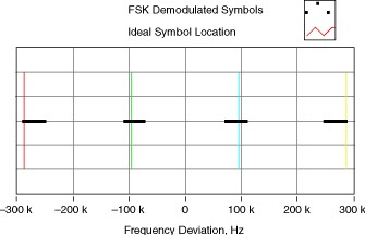
For an M-ary FSK system, the average FSK error is defined as the average root mean squared (rms) spread of the FSK demodulated symbol spaced waveform around the ideal symbol (frequency) locations. Mathematically, the FSK error is defined as:
where:
M is the FSK modulation format, ƒideal,i is the ideal symbol location at the FSK frequency corresponding to location i, and <ƒactual,i> represents the value of the demodulated symbols at location i.

In the figure above, the horizontal lines represent the actual FSK demodulated symbol locations, and the vertical lines represent the ideal symbol locations for a 4-FSK format.
Differential Gain
Unwanted variations in a video signal's chrominance subcarrier's amplitude that result from changes in the signal's DC level, usually specified between 10% and 90% of full scale. Expressed in a percentage, or a fraction of a percentage.
Digital Audio Broadcasting (DAB)
Digital Audio Broadcasting (DAB) is a digital broadcasting standard that began as a European research project during the 1980's. It has evolved into what is commonly referred to as Digital Radio, and is predominately used in Europe at this time. DAB involves taking an analog signal, digitizing it so that it may be compressed using audio codecs such as MP2, and then performing digital modulation before transmitting the broadcast. DAB was invented to address key limitations of the aging FM and AM radio broadcasts. In particular, DAB allows more stations per spectrum which results in more listening options for customers. It also offers better immunity to noise, crosstalk, and other forms of interference which makes it ideal for mobile applications. DAB also offers equivalent or better audio quality than FM radio thanks to reception integrity that does not begin to degrade until the signal drops below a certain power threshold. This is different from FM radio in which reception quality decreases in a linear relationship with the power of the received signal. In 2007, an upgraded version of DAB (simply named DAB+) was released. DAB+ offers improved audio quality via the use of the AAC+ audio codec and implementation of Reed-Solomon error correction.
Error Vector Magnitude (EVM)
Error vector magnitude (EVM) is a measurement of demodulator performance in the presence of impairments. The measured symbol location obtained after decimating the recovered waveform at the demodulator output are compared against the ideal symbol locations. The root-mean-square (RMS) EVM and phase error are then used in determining the EVM measurement over a window of N demodulated symbols.
Field Strength Meter (FSM)
A frequency selective meter for measuring the field strength of transmitted signals. Also called a signal level meter.
Field Strength
The far-field measurement of the electric field or the magnetic field. Units: V/m, A/m or W/m
Frequency Deviation
Frequency deviation quantifies the amount by which a frequency differs from its specified value, as when measuring how much an oscillator frequency deviates from its nominal frequency. In frequency modulation , frequency deviation refers to the maximum absolute difference, during a specified period, between the instantaneous frequency of the modulated wave and the carrier frequency.
Frequency Error, QM
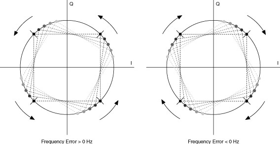
In QM modulation systems, frequency error refers to the difference between the specified carrier frequency and the actual measured carrier frequency. At baseband, frequency error in QM systems is a complex signal impairment that manifests itself as a rotation of the locus of symbol coordinates about the I/Q plane. A fixed frequency offset appears to be a rotation at a constant angular velocity. Frequency error can be either positive or negative in sign, indicating the direction of the rotation.
Frequency Error in a QM System
Frequency Modulation (FM)
Frequency modulation (FM) is a type of angle modulation in which the frequency of a sinusoidal carrier wave deviates from a center frequency by an amount proportional to the instantaneous value of the message signal. In FM, the center frequency is the carrier frequency. Frequency modulation can be expressed using the general equation for angle modulation.

Ac is the carrier amplitude
fc is the carrier frequency
kf is the frequency deviation constant in Hz/V
fm is the frequency of the message signal
For more information on Modulation see the NI RF Help: Modulation.
Frequency-Shift Keying (FSK)
Frequency-shift keying (FSK) refers to a type of frequency modulation which assigns bit values to discrete frequency levels. In noncoherent forms of FSK, the instantaneous frequency is shifted between two discrete values termed the "mark" and "space" frequencies. Coherent forms of FSK exist in which there is no phase discontinuity in the output signal. FSK modulation formats generate modulated waveforms that are strictly real-values, and thus tend not to share common features with QM schemes.
F-type Connector
A threaded, medium-performance coaxial signal connector typically used in consumer applications (TV's and VCR's). This connector is typically usable as high as 1 GHz. It is inexpensive since the pin of the connector is actually the center conductor.
I/Q Data
I/Q is a common way to represent message signals in modern communication systems. As described in the Modulation topic, there are two fundamental ways (degrees of freedom) to produce a modulated wave from a carrier wave. You can either perturb its amplitude or its phase. I/Q signaling allows you to simultaneously change both amplitude and phase. Using both degrees of freedom when modulating a carrier allows greater spectral efficiency with regard to bits per hertz of channel bandwidth (for a given bits per second transmission rate) than if using only one degree of freedom.
For more information on I/Q Modulation see NI RF Help: I/Q Modulation.
Modulation Error Ratio (MER)
The modulation error ratio (MER) is a measure of the signal-to-noise ratio (SNR) in a digitally modulated signal. Like SNR, MER is usually expressed in decibels (dB). MER over number of symbols N is defined as:
Noise Figure
The noise figure (NF) is the ratio, in decibels (dB), of the actual output noise to the noise that would remain if the instrument did not contribute its own thermal noise. If you terminate a unit under test (UUT) input with a matched resistive load (typically 50 &ohm) and measure the noise power density (watts/Hz) at its output (No), the NF is given by the following equation:

where G is the power gain (in linear units) of the UUT, k ≈ 1.38 ×10⁻²³ is Boltzmann’s constant, and T ≈ 290° K is the ambient temperature. In heterodyne systems, output noise power includes spurious contributions from image-frequency transformation, but the portion attributable to thermal noise in the input termination includes only that which appears in the output via the principal frequency transformation of the system, and excludes that which appears via the image frequency transformation.
Phase Modulation (PM)
Modulation is a process that alters the characteristics of a carrier wave according to information in the message signal, m(t), to generate and transmit a modulated wave. There are several types of modulation.
The phase-modulated carrier signal is represented by the following equation:
where m(t) is the time-varying message signal, Ac is the amplitude of the carrier wave, and fc is the frequency of the carrier wave.
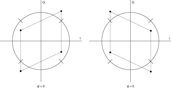
Quadrature Error
In a QM -modulated system, quadrature error, also referred to as quadrature skew, describes a complex signal impairment such that the I and Q components are not perfectly orthogonal. Quadrature error can be either positive or negative, with the sign indicating the orientation of the error.
Quadrature Skew
RF Multiplexer
A switch capable of selecting one of many RF channels.
Rho
ρ is a measurement that evaluates modulation quality. To calculate ρ find the correlation between the recovered waveform and an ideal waveform that has been reconstructed from the demodulated bits. That is, compare the received demodulated waveform to an ideal waveform obtained by re-modulating the output bit stream of the NI Modulation Toolkit digital demodulation VI. The ρ measurement is related to error vector magnitude (EVM): while EVM measures the vector difference between the measured and ideal signals, ρ measures the correlation between the two signals. The value of ρ can range from 0.0 to 1.0.
Table 1. ρ Values
| Value | Meaning |
| ρ = 0.0 | uncorrelated |
| 0.0 < ρ < 1.0 | partially correlated |
| ρ = 1.0 | perfectly correlated |
Smith Chart
You use Smith charts to study transmission line behavior. A transmission line is a medium through which energy and signals are transmitted. A transmission line might be a wire, or it might be the atmosphere through which a signal is transmitted. Each of these transmission lines has an effect on the signal that is being transmitted. This effect, called the impedance of the transmission line, can attenuate or phase shift an AC signal. A transmission line has an associated impedance, a measure of the resistance, and the reactance of the line. The impedance is commonly listed as a complex number of the form z = r + jx. In this equation, z is a complex number that represents the impedance, and contains both resistance (r) and reactance (x) components. You can use the Smith plot to plot impedances of transmission lines. The plot consists of circles of constant resistance and reactance. You can plot a given impedance, r + jx, by locating the intersection of the appropriate r circle and x circle. Once plotted, you can use the Smith plot as a visual aid to match impedance, and to calculate the reflection coefficient of a transmission line.
YIG
Yttrium-Iron-Garnet. A crystal whose resonance frequency is linearly proportional to the DC magnetic field that it is exposed to. This tunable oscillator is typically used in the microwave frequency range.
Zero Index (Quadrature)
The zero index is a reference position on most quadrature encoders used to determine position. When the encoder passes this index position during a revolution, it pulses the Z-terminal of the device. This single pulse per revolution allows for the user to determine the position of the encoder, whereas the A and B channels of the encoder are used to determine rotational direction. Units: rad


