From Saturday, Nov 23rd 7:00 PM CST - Sunday, Nov 24th 7:45 AM CST, ni.com will undergo system upgrades that may result in temporary service interruption.
We appreciate your patience as we improve our online experience.
From Saturday, Nov 23rd 7:00 PM CST - Sunday, Nov 24th 7:45 AM CST, ni.com will undergo system upgrades that may result in temporary service interruption.
We appreciate your patience as we improve our online experience.
TSN is the evolution of standard Ethernet—specifically the IEEE 802.1 standard—to add capabilities such as time synchronization over the network and deterministic, low-latency communication to the open network of Ethernet. TSN synchronization is provided through the IEEE 802.1AS standard, which is an IEEE 1588 profile that provides a common notion of time on all the nodes within the IEEE 802.1AS subnet. This synchronization of multiple nodes uses packet-based communication and is possible over long distances without signal propagation delay impact.
TSN was introduced to NI-DAQmx-based devices starting with NI-DAQmx 17.1, allowing a simple way to synchronize your distributed measurement systems over the network. Because all devices on the IEEE 802.1AS subnet have a shared notion of time, you can now use time as a trigger for the first time. Using time as a synchronization method provides a simplistic approach to correlating data from multiple devices with a known amount of uncertainty.
I/O synchronization on devices using this IEEE 802.1AS is less than 1 μs, but this can be greatly reduced to the hundreds of nanoseconds range depending on the configuration of the system.
Because clocks cannot be shared directly over the network, TSN-based devices synchronize by measuring and adjusting the relationship between their clock and a reference clock on the network. Although this is a reliable and accurate method, it is fundamental to synchronization performance in TSN systems.
In the IEEE 802.1AS specification, the reference clock—referred to as the grand master (GM) clock—is automatically selected through an election algorithm. The election is based on clock quality, traceability, and priority; if there happens to still be a tie after those are announced, then it comes down to the MAC address of the device.
After the GM is selected, all other devices become slaves and begin adjusting their clocks to follow the GM clock. The result of the adjustment is additional low-frequency phase noise is introduced to the clocks being used on the slaves. However, NI ensures that all C Series module and FieldDAQ device (no longer sold) specifications are met when used in NI hardware within supported network topologies with the NI device acting as the GM. You should verify performance in any other situation.
When designing a distributed synchronized measurement system, one of the first things to consider is how all these devices are connected to each other, otherwise known as your system topology. As you are designing your system topology, consider the number of hops in the system. A hop is created as the number of devices increase in a line within the topology, which increases the number of bridges participating in the synchronization. In the following image, the system consists of two hops (assuming the first chassis is the GM).
Figure 1: A TSN topology that consists of two hops (assuming the first chassis is the GM)
Each additional hop, or bridge introduced into the system, adds tens of nanoseconds of uncertainty into the synchronization accuracy. When you review the three main topologies, the line topology has the greatest amount of bridges introduced and participating in synchronization, providing the lowest synchronization accuracy of the three main topologies. The star topology provides the highest synchronization accuracy because there is only a single hop between the GM and the devices. The ring topology adds a redundant link that is exploited automatically to improve the data movement and synchronization, allowing the lowest possible number of hops away from the GM to the furthest device.
Learn more about the system topologies and designing distributed TSN measurement systems.
To support the broadest possible set of measurement types and channel densities, C Series modules and FieldDAQ devices (no longer sold) are supported using several different timing architectures. There are two groups of timing architectures: sample clock timed and oversample clock timed. Both timing architectures rely on clocks to control when samples occur. In most cases, the chassis generates the necessary clocks. On synchronized TSN devices, these chassis clocks are tuned to the same reference frequency, that of the GM, and thus maintain a fixed-phase relationship.
Sample clock-timed modules are operated from a sample clock generated by a timing engine on the chassis. Because the sample clock is derived from a time base that is phase-aligned with the TSN network, the clock is synchronized with other clocks on the IEEE 802.1AS network. The sample clock starts running when a start trigger event occurs. When the start trigger is shared by modules, the data is synchronized. When the modules are identical, the data reflects precisely aligned samples. For different module types, the delays may be different, which affects the precision of the data.
Scanned modules, types of sample clock-timed modules, adds per-channel delays as the single analog-to-digital converter (ADC) must operate separately for each channel being acquired. When synchronizing scanned modules with nonscanned modules, care must be taken to associate samples from the scanned module and other module types.
Oversample clock-timed modules operate from high-precision clocks that run constantly. On TSN devices, these clocks are generated by the chassis itself and are tuned to match other chassis clocks but are not phase aligned. They do not drift from each other, but may be misaligned by up to half a sample period between chassis. Because the clocks run constantly, another signal is required to synchronize the data from these clocks, the sync pulse. This signal indicates when the module should start producing or consuming data. Without this signal, the clock would be synchronized but not the data.
Most oversample clock-timed modules are DSA modules, which oversample and filter to produce the final data. This introduces group delay, which can vary between module types and different configurations of the same modules. On C Series NI-DAQmx modules and FieldDAQ devices (no longer sold), this group delay is present in the data affecting the precision of synchronization.
Learn more about synchronizing analog input C Series modules with NI-DAQmx.
Devices that do not support IEEE 802.1AS cannot synchronize directly with TSN devices. For example, in the following system, the CompactDAQ TSN chassis, which also applies to FieldDAQ devices (no longer sold), are synchronized to each other but not to the PC running NI-DAQmx. To help with this, the NI-DAQmx driver tracks the relationship between time on the devices it controls and time on the host where it executes. This results in two different timescales: host time on the host (PC), and I/O device time on the CompactDAQ chassis.
Figure 2: The cDAQ-9185 and cDAQ-9189 both use the IEEE 802.1AS profile for synchronization
In this configuration, host time is driven by an oscillator on the PC and corrected periodically using the Network Time Protocol (NTP) to match the time on an Internet server. This time is always close to actual time but jumps during time corrections such as daylight savings. I/O device time is driven by an oscillator on one of the CompactDAQ TSN chassis and is corrected periodically to follow time on the GM. The configuration of the GM determines the properties of this time. If the GM is a cDAQ-9185/9189 chassis, this time starts counting from zero (interpreted as January 1, 1970) when the chassis is powered on and then drifts relative to actual time. This makes measurements consistent, but means timestamps taken in I/O device time cannot be directly compared to actual time.
NI-DAQmx translates timestamps between host time and I/O device time as necessary. The accuracy of this translation is determined by the consistency of the clocks in question, and whether the timestamp is in the past or future. Timestamps in the past are normally translated to within a millisecond. For timestamps in the future, NI-DAQmx must extrapolate the future relationship, which introduces additional error.
Applications that cannot tolerate this error can use I/O device time directly, or use a host that can act as an IEEE 802.1AS GM. Using I/O device time directly requires special programming to measure the current I/O device time and operate on the timestamps. A simpler approach is to use host time on an NI controller that supports IEEE 802.1AS such as CompactRIO controllers that support NI-DAQmx or cRIO-9039. These controllers set their host time from an onboard real-time clock, so it is close to actual time and defaults to being the GM. This removes all sources of error in timestamp translation.
When working with timestamps in LabVIEW, it is important to be aware of the data type being used to store and manipulate the timestamp. The timestamp type in LabVIEW has a 64-bit field for seconds and another 64-bit field for fractional seconds. A value in this type represents the number of seconds after the LabVIEW epoch (January 1, 1904). You can convert this type to a DBL or EXT floating point type, which have 64 bits and 80 bits, respectively. However, these types cannot hold all the time values that the timestamp type can and lose accuracy in some cases.
Hardware also introduces limitations. In general, clocks are phase aligned to time so that edges appear on even-second boundaries. This means that clocks cannot drive behavior at any arbitrary time. For example, a 40 MHz clock can only trigger or timestamp events on 25 ns boundaries.
Together, these effects can cause significant unexpected error in timed operations when synchronization within 1 μs is required. For time start triggers, the most reliable way to deal with these effects is to compare the configured time with the coerced time, which is available with the NI-DAQmx start.time.when property.
The simplest way to achieve tight synchronization in a time-based distributed measurement system is to use multidevice tasks, also known as channel expansion. In this case, NI-DAQmx software accounts for most of the impacts described previously and achieves synchronization within 1 μs in common synchronization use cases.

Figure 3: A channel expanded NI-DAQmx task consisting of channels from two chassis
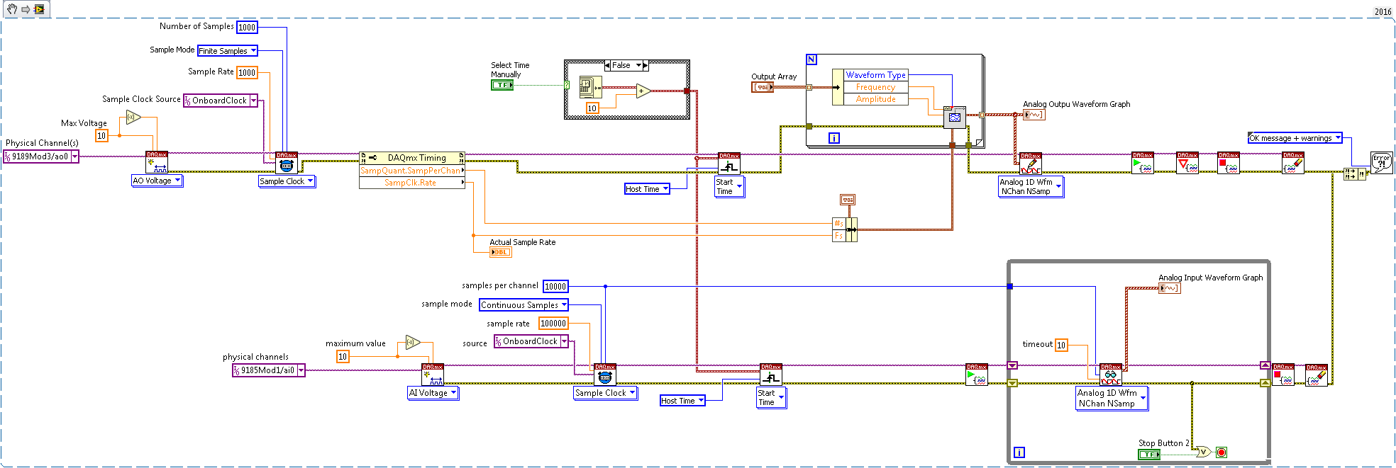
There are several exceptions and use cases where more precise synchronization is required past the channel expansion case. One limitation of channel expansion is mixing different measurement types. For example, if both DI and AI are required to be synchronized, multiple tasks must be used for each measurement type. In this case, the simplest way to synchronize the two tasks is to specify identical start trigger times.

Image 4: Synchronizing two different channel types using NI-DAQmx
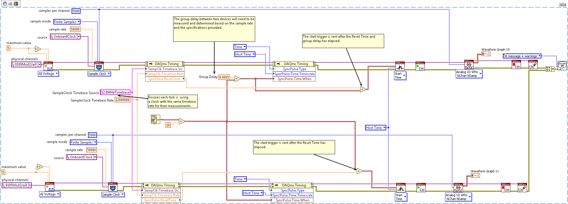
Another limitation of channel expansion is when you must address group delay with DSA modules. However, this delay can be corrected by using a separate task for the DSA module channels with a sync pulse time adjusted by the amount of the delay. This delay must be measured and can be adjusted only within the precision allowed by the oversample clock.

Figure 5: Adjusting for group delay between modules using NI-DAQmx
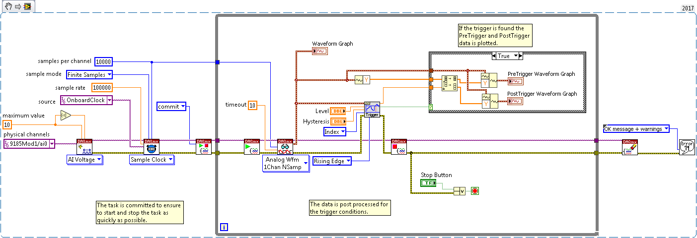
Timed-based start triggers do not allow for pre-triggered samples like reference triggers do. Timed-based NI-DAQmx systems do not support reference triggers over the network, because there is no path to propagate the trigger. However, the same result can be achieved by starting all input channels well before the reference trigger signal, post-processing the data to seek the trigger, and then discard anything outside the pre- and post-trigger windows. This can be done by using the Basic Level Trigger Detection.vi function to identify if the trigger condition occurred.

Figure 6: Using post-processing to simulate a reference trigger for a task with NI-DAQmx
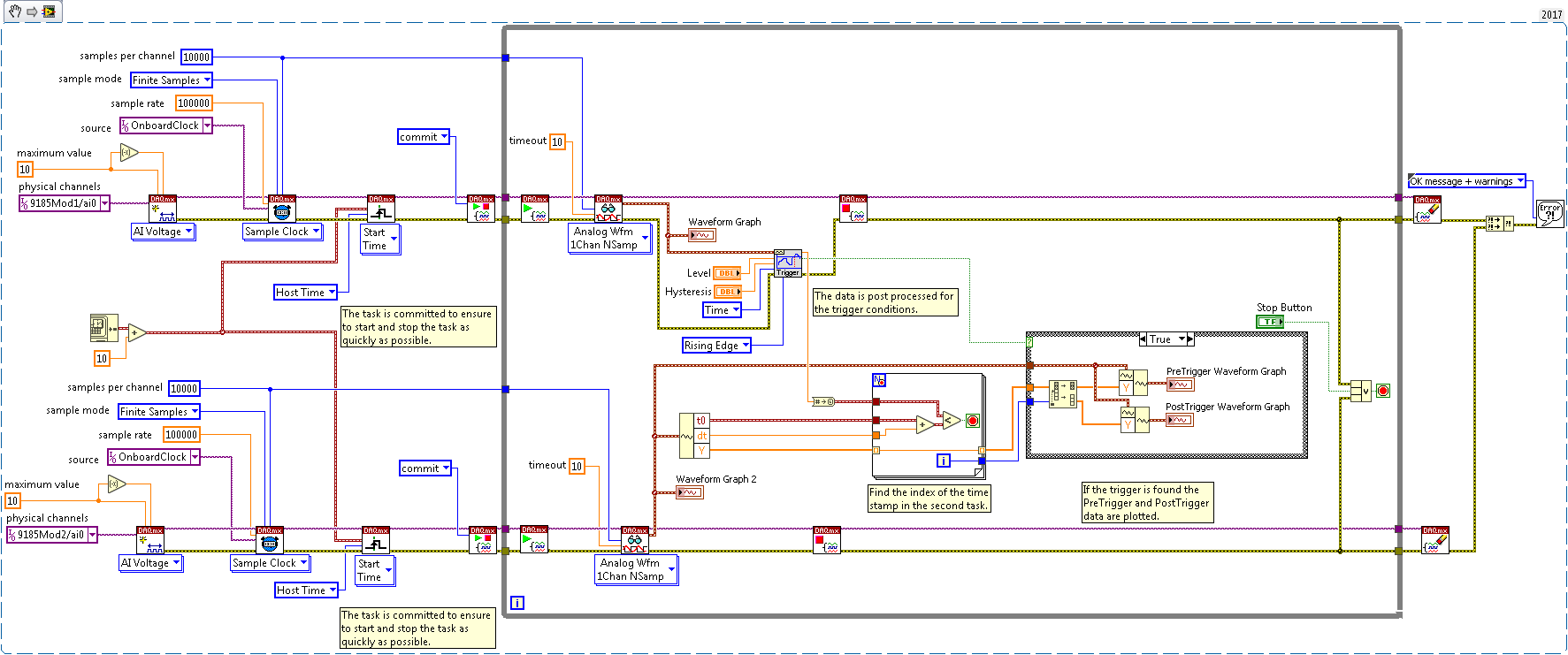
If the trigger condition and data to be captured occur on different modules or different chassis two tasks can be used to identify the trigger and also separate out the corresponding data. All input channels need to be started well before the reference trigger signal, timestamping the input signal using a counter or other means, and then post-processing the data to discard anything outside the pre- and post-trigger windows. This can be done by comparing the timestamp of the trigger with the timestamp of each sample calculated using the first sample time and sampling period.

Figure 7: Using post-processing to simulate a reference trigger for a task using a timed-based start trigger with NI-DAQmx
For other use cases, correlating data using time is the best approach. The time for each sample can be calculated from the time of the first sample and the period of the I/O operation. When using time start triggers, the configured time can be used as the first sample time, or the start.time.when property if start time coercion is important. If greater accuracy is required, a counter should be configured to timestamp the first edge of the sample clock or sync pulse. As a convenience, the t0 of a waveform will contain an approximation of this value.
The registered trademark Linux® is used pursuant to a sublicense from LMI, the exclusive licensee of Linus Torvalds, owner of the mark on a worldwide basis.