Using LabVIEW and PXI to Create an Automated CAN Communication Test System for Sensor Boxes in Modern-Day Vehicles
Joey Nino N. Aguila, Global Inventive Technologies Int'l Inc.
"With the numerous benefits of National Instruments software and hardware products, creating our test and measurement system was effortless. NI products are flexible and user-friendly and integration with third-party products was also straightforward by using LabVIEW drivers that were readily available online."
- Joey Nino N. Aguila, Global Inventive Technologies Int'l Inc.
The Challenge:
Developing a high-speed test and measurement system for automatic, simultaneous data acquisition with distributed controller area network (CAN) measurement signals on up to six sensor boxes in a controlled temperature chamber.
The Solution:
Using NI LabVIEW software and PXI hardware to acquire data from the device under test (DUT) through CAN signals and to control the temperature settings of the benchtop temperature chamber using a single frontend software.
With NI PXI modular instruments, we don’t have to worry about high-speed data acquisition or timing and synchronization because NI products take care of these issues for us. The hardware runs as fast as 30 ms as required in this test setup. Because LabVIEW uses a dataflow paradigm, simultaneous and/or parallel code execution is now possible as an alternative to text-based, sequential programming. We can control and/or monitor multiple instruments and devices at the same time. Instrument integration is more manageable because most benchtop instruments, including the one used in this test system, have a LabVIEW driver available online. With these advantages, we can focus on smoothly developing the functionality of our system.
Main Concept
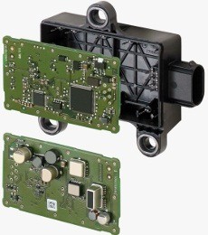
The DUT in this system is a sensor box (see Figure 1), which is installed in a modern-day vehicle that gives lateral and longitudinal acceleration, yaw rate, roll rate, and x-, y- and z-direction measurements. This DUT requires some internal processing before passing it through CAN signals in the engine control unit (ECU), which acts as the vehicle’s main controller to interpret information and execute actions just like the human brain.
The testing principle is simple. An analyst engineer places the DUT, which can be connected to a CAN instrument, inside the chamber and then sets the desired temperature setpoint. The engineer then views the readings via CAN communication and records and saves the data on a local hard drive in Microsoft Excel for further analysis. Because the chamber itself cannot be programmed for two or more setpoints, the engineer must manually set it. Additional test procedures might involve performing a power ON reset (POR) on the DUT at a specific time to observe how it reacts or acquiring readings every 30 ms, which requires high-speed hardware.
Significance of Testing
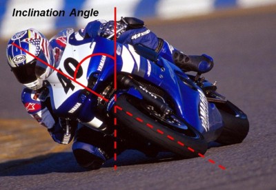
The main DUT function is to provide certain readings related to the center of gravity and speed when the vehicle is in motion, especially when zigzagging or on a road with a banking angle. The ECU evaluates the readings to correct the position of the vehicle’s shafts or wheels to prevent it from skidding (see Figure 2).
The DUT function involves human lives, so it is crucial that the device always perform accurately, even in extreme temperatures. This is the reason we test the devices for functionality in the laboratory before mass producing it.
System Description
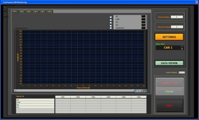
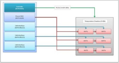
Our system controls and monitors the ramp up and down temperature of the chamber, sources and measures voltage in the DUT, and acquires high-speed data through CAN communication (see Figure 3). Other system features include a real-time graph viewer and data logging in Excel.
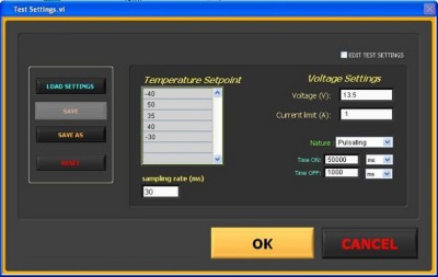
The analyst engineer enters the test settings (see Figure 4) and clicks OK to start acquiring data. The system automatically stops and saves the data on the local hard disk, so the engineer does not need to be present during the test. The system can perform the analysis after the test is finished. National Instruments software and hardware products are well suited to our system specifications and configuration. Because all the hardware, such as the controller, SMU, and CAN interfaces, is integrated in a compact chassis, it reduces the space occupied in the test lab, which is a great advantage in a small area.
System Design
We created an automated test and measurement system that can test multiple sensor-box devices under controlled temperature. It can perform simultaneous data acquisition of up to six devices in a customized test setting (see Figure 5).
We chose a 2-slot NI PXI embedded controller instead of a commercial PC because of its ruggedness, performance, modularity, and low cost. The CAN data acquisition is performed using an NI PXI solution for CAN. The NI PXI-8513/2 is a 2-port, software-selectable CAN PXI interface. It is well suited for real-time, high-speed manipulation of hundreds of CAN frames and signals, which is required for applications like hardware-in-the-loop simulation, rapid control prototyping, bus monitoring, and automation control. The software-selectable characteristics of this module provide the best flexibility for CAN development with onboard transceivers for high-speed, low-speed/fault tolerant, and single-wire CAN. This flexibility is more than enough for the 30 ms data acquisition required for this application.
We used the NI PXI source measure unit (SMU) to provide power to the DUT. It can source up to ±20 V, 2 A maximum with the auxiliary power supply. This is a shared power supply among the six CAN channels.
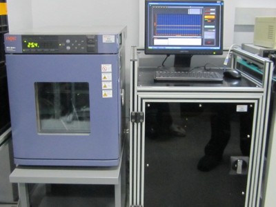
The ESPEC SU-241 benchtop temperature chamber uses balanced temperature control. The system balances temperature to recreate the desired environmental conditions inside the test area. This is done by continually controlling a low-heat load heater. Each unit is controlled in real time to balance the temperature. Moreover, the refrigerator capacity is continually updated to counter the heat load of specimens with minimal energy. This chamber is connected via RS232 in the controller.
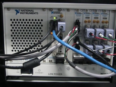
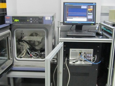
Figure 6 shows the final PXI hardware configuration of this test system. All of the required modules are housed in a single PXI chassis, greatly reducing the overall size. This setup also connects all the essential instruments via the PXI backplane for faster performance and throughput.
Automated test configuration through the CAN, the SMU, and the chamber is done in frontend software we developed in LabVIEW. The dataflow execution of this programming language makes simultaneous and parallel readings of multiple sensor-box devices possible. This unique feature is extraordinary because it gives the software developer the capacity not just to read multiple CAN signals from every device, but also to control and monitor the set temperature of the chamber and the voltage supply of the SMU simultaneously, rather than sequentially.
Conclusion
Thanks to LabVIEW, the days of memorizing programming syntaxes, sequential code execution, and the mentally taxing process of debugging programs are gone. Code development is much easier now, saving us time and money. LabVIEW also gives us the power to reuse our previous code to shorten development time.
The NI hardware we chose was ideal for our demanding, high-priority industrial application. Its modularity, ruggedness, and high performance were the main reasons we chose it for this PXI-based industrial application. PXI modules and controllers are designed to run for long hours and were a perfect fit for our application.
With the numerous benefits of National Instruments software and hardware products, creating our test and measurement system was effortless. NI products are flexible and user-friendly and integration with third-party products was also straightforward by using LabVIEW drivers that were readily available online.
Author Information:
Joey Nino N. Aguila
Global Inventive Technologies Int'l Inc.
Blk 6 Lot 3, Mountview ave. cor. Mayon St. Mountview Insdutrial Complex Bancal, Carmona
Cavite
Philippines
Tel: +63 046 430 3617
Fax: +63 046 4303617
joey.aguila@fujimaster.com
