High-Voltage, Time-Dependent Dielectric Breakdown System for the IEC 60747-17 Standard
Flavio Floriani, INTEK S.p.A. Laboratory, Sector Manager
"Thanks to the RIO platform provided with FPGA technology and powered by LabVIEW development environment, we have developed a system with 4 functional levels."
- Flavio Floriani, INTEK S.p.A. Laboratory, Sector Manager
The Challenge:
INTEK needed to invent and build a fully automatic measurement system that could test up to 50 magnetic couplers simultaneously while they are subjected to a high voltage (up to 8 kV rms) and placed in a 150 °C oven. The system also needed to record the mean time to fail and monitor the overvoltages generated when a device breaks.
The Solution:
INTEK used the CompactRIO platform with FPGA technology and LabVIEW to develop a system with four functional levels. The system combines the power of NI hardware with the flexibility of LabVIEW.
The use of a magnetic coupler, or the device under test (DUT), is similar to that of an optocoupler. It must guarantee the insulation between two points at different potentials to satisfy the security standard (SOT-24 package). A test required in the reference standard is to estimate the mean time to fail (MTTF) by applying a 50 Hz sinusoidal high voltage and record the time to breakdown. Once a consistent number of data is collected using a statistical technique, we can parametrize a Weibull distribution and predict lifetime. When a failure occurs, the DUT looks like a short circuit (an internal discharge path shorts the two points), and when the DUT is in normal condition it looks like a small capacitor.

After three years of study on how to manage the AC high voltage (up to 8 kV rms) on these small DUTs (simpler 15-position equipment have run continuously for two years and collected a lot of data), we can focus on the main issues emerging from these kind of tests:
- How to cut the current that flows through a DUT when it fails, without generating an extravoltage (which could damage all the other DUTs)
- How to use only low voltage components to have small equipment dimensions and low cost
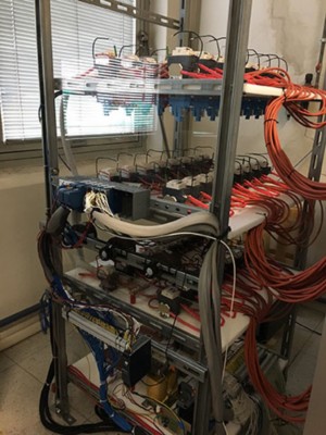
- How to manage all the wirings and safely merge high-voltage circuits with extra low voltage circuits
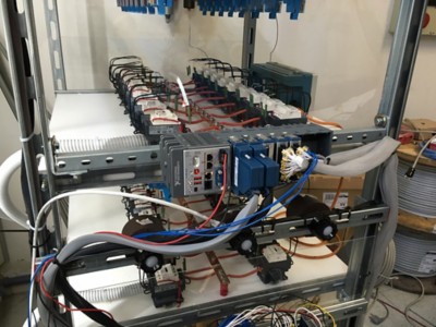
Combining the result of these studies with NI technologies, we have developed a system architecture that includes a cRIO-9035 controller and two NI-9205 analog input modules to read the current in each of the 50 circuits and read the high voltage. We acquired the current by reading voltage drop on shunt resistors and acquire the voltage by reading the output of a customized high-voltage divider developed specifically for this application. The system also includes two NI-9476 digital output modules to command the 50 relays that cut off the current when a breakdown occurs. We also used an NI-9217 RTD module to acquire the temperature inside the oven through a PT100.

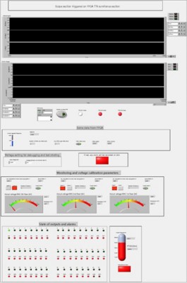
We developed a four-level software architecture using LabVIEW. An FPGA runs the part of code that detects the fault current and commands the cut-off relay. Because we need speed and determinism, the FPGA is perfect for this application. With some optimization, we finally read the RMS fault current (calculated on 60 ms perdiod) and ensured the fault clearing in less than 100 ms. It is important to clear the fault quickly because the current damages the DUT and the customer needs to analyse them after the test to study and improve the technology. We developed a kind of scope with a pre-trigger function and ran it in a parallel loop. Every 100 ms, the scope controls the insantaneous maximum voltage value and eventually records and saves the waveform if the threshold alarm is exceeded. We can easily edit all the scope parameters such as pre-trigger time, sample rate, and more in the front panel. We used DMA and FIFO structures to have high speed and share data in the project. We also monitored the oven temperature with a lower sample rate in another parallel loop and compared with an alarm threshold.
Every time a DUT fails, the FPGA VI changes the state of a shared variable in the project and the VI detects it running on the real-time enviroment. By using the real-time features, we could easily create a VI that automatically acquires the time to fail and saves it directly on a file on the CompactRIO system. This makes it easy to download that file during or at the end of the test and have all the required information. The real-time VI is an auto-running executable on the system and has no user interface, which ensures stability.
We created another VI inside the project and converted it to an EXE file. This VI can be run on any PC connected to the same LAN network to control the state of the whole system (alarms, state of DUT, overvoltages, temperature, and more). The technicians can easily monitor the test status every day or when needed (a test session can go on for longer than two months). It can be used also during the debug operations.
We also created a VI with the channel status only and converted it to a web page. The customer can connect directly to the system and know the status of the DUT, but cannot interfere with the apparatus settings.

Results:
We satisfied our customer and powered useful data collection, consistent with the statistical model. We also improved technology and reduced test costs. We may possibly deposit a patent.
Author Information:
Flavio Floriani
Find this author in the NI Developer Community