Region Of Interest Frequently Asked Questions (FAQ)
Contents
- What Is a Region of Interest?
- Why Do I Get an Error Using IMAQ Read Barcode VI?
- Why Does the IMAQ Transform ROI VI Return Negative Coordinates?
- Why Is My Image Too Large to Use the CWIMAQVision.MaskToRegions Function in Visual Basic?
- How Do I Extract a Free Shape ROI?
- How Do I Display a Selected ROI in a New Window?
- Why Do I Get Inaccurate/Differing Values When Using the Clamp Function?
- How Do I Create a Rectangular ROI from a Set of Points in LabWindows/CVI?
- How Do I Build an ROI from a Contour in Labwindows/CVI?
- How Do ROIs Operate with Optical Character Recognition (OCR)?
What Is a Region of Interest?
A Region of Interest (ROI) is an area of an image, which is graphically selected from a window displaying that image, in which you want to focus your image analysis. This area can be used to focus further processing. The following document contains information about ROI functions and the way they are used.
Why Do I Get an Error Using IMAQ Read Barcode VI?
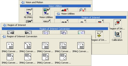
You will get error -1074395720 IMAQ Read Barcode, Invalid ROI when using IMAQ Read Barcode VI if the ROI descriptor passed is incorrect. The best way to solve this is to use a VI to convert a shape into an ROI in order to output the correct ROI descriptor. You can use a VI located in the Region of Interest Conversion sub-palette. This palette can be found in LabVIEW by going to Functions»Vision and Motion»Vision Utilities»Region of Interest»Region of Interest Conversion.

Why Does the IMAQ Transform ROI VI Return Negative Coordinates?
When you use the IMAQ Transform ROI VI to rotate an ROI, the VI may return an incorrect result and give negative coordinates for the ROI. If this happens, you should make sure that you are using the most recent version of NI Vision that is supported by your version of LabVIEW. A full list of compatible NI Vision and LabVIEW versions can be found in LabVIEW, LabWindows/CVI and Vision Development Module Compatibility.
Why Is My Image Too Large to Use the CWIMAQVision.MaskToRegions Function in Visual Basic?
This function transforms a mask image into a regions collection. By default, it has a limit of 2500 points. If you would like to use more than 2500 points, you can set the parameter MaxPoints to the value that you would like to use. As an alternative, you can break your image into multiple images, and then do your processing in segments. A full description of all Vision functions and their properties and methods can be found in the NI Vision for Visual Basic Reference Help. This will be installed on your computer by default if you have NI Vision installed. I can be found by going to Start»Programs»National Instruments»Vision»Documentation»NI Vision. Open the file called cwimaq.chm.
How Do I Extract a Free Shape ROI?
The image data type in NI Vision currently supports rectangular images; this means that image data must be stored in 2D array form. Due to this, most users will choose to select and extract rectangular ROIs.
A quick method of extracting an ROI involves obtaining a rectangular ROI descriptor using IMAQ Construct ROI VI, this descriptor can be fed into IMAQ Extract Tetragon VI which extracts the ROI from the original image. This method is specific to extracting rectangular ROIs; a more robust means of extracting ROIs is described below.
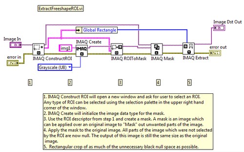
Freeform, non rectangular, ROI descriptors are also obtained using IMAQ Construct ROI VI. In order to extract non rectangular ROIs special steps are taken after obtaining the ROI descriptor; this is described in the figure below. The ROI descriptor is converted to a mask, the mask is applied to the original image, and a rectangular crop is made around the ROI. ExtractFreeshapeROI.vi will take an image as an input, ask users to select the ROI in a new window pop-up and output the extracted ROI as a new image. More information can be found at the Community Example: Extracting a Freeshape ROI.

How Do I Display a Selected ROI in a New Window?
You can display an ROI in its own window if you can get the ROI Descriptor. The ROI Descriptor is a specific data cluster that IMAQ uses to carry the position location for an ROI. It is available as an output on several IMAQ VIs, including IMAQ ConstructROI, IMAQ WindGetROI, IMAQ MaskToROI, and any VI in the Functions»Vision and Motion»Vision Utilities»Region of Interest»Region of Interest Conversion sub-palette. If using Vision Acquisition Software 2009 or later, you will have access to the IMAQ Extract Tetragon VI. As seen below, the IMAQ Extract Tetragon VI takes the ROI Descriptor as a direct input and extracts the image within the area defined by the ROI Descriptor. The IMAQ WindDraw VI then takes this image and displays it in a separate image window.
If you are using a version of Vision Acquisition Software prior to 2009, there are a couple additional steps that you'll need to complete to display the ROI in a separate window. First you need to unbundle the ROI Descriptor cluster to get the Contours array. If you index this array, you can get a cluster which contains the Coordinates array. These coordinates describe the rectangular location for the ROI. If you use these coordinates and the IMAQ Extract VI, you can create a new image that contains only the region of the first image contained in the specified coordinates (which is the ROI). You can display this new image in its own window by using the IMAQ WindDraw VI.
Both of these methods can only be used with rectangular ROI selections. If you would like to display an ROI that isn't rectangular you can use the IMAQ WindDraw VI in conjunction with the ExtractFreeshapeROI.vi example discussed above.
Why Do I Get Inaccurate/Differing Values When Using the Clamp Function?
When you draw an ROI around a particular object with the Clamp function in Vision Assistant, you get a particular measurement value for the distance. If you draw a different ROI around the same object, you may get a different measurement than the first. This is due to the line profile spacing in the clamp. These line profiles run across the distance of the clamp and return the first edge they encounter. The more spread out the line profiles, the more likely the clamp will miss the actual maximum or minimum point on the contour to be measured. When a new ROI is drawn, the line profiles are shifted slightly, so a different value may be read.
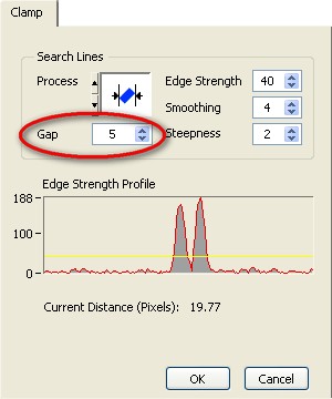
To avoid this issue, lower the Gap value in the clamp function. This will decrease the space between line profiles. When decreasing the Gap value, the measurement will have higher precision, but will take more processing time. Use a larger Gap value for straight edges or objects with little variance. Use a lower Gap value when measuring objects with detailed features or angles that might be missed.
Note: When using the Clamp VIs in LabVIEW, the Gap value is referred to as the Subsampling Ratio, and can be found in the Settings cluster.
How Do I Create a Rectangular ROI from a Set of Points in LabWindows/CVI?
The ROI datatype is not explicitly defined in LabWindows/CVI, but you can access and modify ROIs by using the Vision function calls.
For example, the following code demonstrates how to set a rectangular ROI:
Rect rect = { 80, 10, 55, 340 };
ROI* roi = imaqCreateROI();
imaqSetWindowROI(Display, roi);
A full description of all Vision functions and their properties and methods can be found in the NI Vision for Visual Basic Reference Help. This will be installed on your computer by default if you have NI Vision installed. It can be found by going to Start»Programs»National Instruments»Vision»Documentation»NI Vision. Open the file called cwimaq.chm.
How Do I Build an ROI from a Contour in Labwindows/CVI?
The ROI datatype is not explicitly defined in LabWindows/CVI, but you can access and modify ROIs by using the Vision function calls .
For example, the following code demonstrates how to convert a contour into a ROI:
const int numPoints=3;
Point myArrayofPoints [3] = {MakePoint( 1,2),MakePoint( 3,4), MakePoint( 1,5)};
ROI* roi = imaqCreateROI();
imaqAddClosedContour( roi, myArrayofPoints , numPoints) ;
A full description of all Vision functions and their properties and methods can be found in the NI Vision for Visual Basic Reference Help. This will be installed on your computer by default if you have NI Vision installed. It can be found by going to Start»Programs»National Instruments»Vision»Documentation»NI Vision.
How Do ROIs Operate with Optical Character Recognition (OCR)?
OCR is divided up into two distinct sections: training and reading. During the training procedure, the ROI specifies the region in which the objects are that you want the computer to learn. During reading, the ROI is the region in which the computer will look for data to read. You can manipulate the ROIs to effectively increase the accuracy and efficiency of the OCR process. During training, you can use the ROI to carefully specify the region in the image that contains the objects you want to train while excluding noise and extraneous objects. During reading, you can use the ROI to enclose only the objects you want to read which reduces processing time and increases accuracy.


