Frequency Measurements Guide - How is Frequency Measured?
Contents
- Frequency Overview
- How to Make a Frequency Measurement
- Recommended Hardware and Software
- Frequency Webcasts Tutorials, and Other How-To Resources
Frequency Overview

Figure 1: AC Electronic Load
Frequency is usually represented as angular frequency ω in radians/second, or as ƒ in seconds-1, also known as the unit hertz (Hz). You also can use beats per minute (BPM) and revolutions per minute (RPM) to represent frequency. Angular frequency ω (rad/sec) and ƒ (Hz) are related by the following formula: ω =2πƒ. Frequency is also spoken of in correlation to a phase φ, which describes an offset of the wave from a specified reference point at the initial time t0, and is usually given in degrees or radians. Taking the example of a sinusoidal wave, the waveform function is expressed in terms of time as![]() , with amplitude A, angular frequency ω, and phase φ as constants.
, with amplitude A, angular frequency ω, and phase φ as constants.
Periodic analog signals in real applications are complex and can rarely be represented by a simple sinusoid. Fourier analysis is used to decompose any complex waveform into a sum of simpler functions, either sines and cosines or complex exponentials. The frequency components that make up such a signal are often the properties of interest, and this analysis is known as frequency-domain or spectral analysis. This type of analysis is required mainly for sound and vibration and is not examined in this white paper.
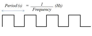
Obtaining the frequency of a digital signal, on the other hand, is quite simple. For a simple digital signal, such as the one depicted in Figure 2, the period is simply the time between rising edges, or even falling edges.
Figure 2. Digital Waveform
If the time between rising or falling edges varies slightly, you can average it over a large number of samples to determine the frequency.
How to Make a Frequency Measurement
For a digital frequency acquisition, the process is fairly simple. For low-frequency signals, it is sufficient to use one counter, or timebase. The rising edge of the input signal triggers the number of timebase ticks to be counted. Because the timebase is of a known frequency, you can easily calculate the frequency of the input signal (see Figure 3).
Figure 3. Digital Signal with Respect to Internal Timebase (One Counter for Low Frequency)
When the frequency of the digital signal is very high or varies, it is better to use one of the two-counter methods described below. Note that the same hardware limitation applies to both two-counter methods. That is, the frequency you are measuring cannot exceed the maximum input frequency supported by the counter, even though it may exceed that of the internal timebase.
High-Frequency Two-Counter Measurement Method
For a high-frequency signal, you need two counters. A paired counter (two counters) generates a pulse train with a user-specified period, “measurement time” (see Figure 4), much larger than that of the signal you are measuring but small enough to prevent counter rollover.
Figure 4. Digital Signal Frequency Measured with Two Counters (High Frequency)
The measurement time of this Internal Signal should be a multiple of the Internal Timebase, or, in other words, divided down. The number of ticks of the Input Signal is then counted over the known period of time provided by theInternal Signal. Dividing the number of ticks by the known measurement time gives the frequency of the Input Signal.
Large-Range Two-Counter Measurement Method
For signals with variations in frequency, this two-counter method provides increased accuracy throughout the entire range. The Input Signal in this case is divided by a known value, or divisor. The number of ticks of the Internal Timebase is counted over one logic-high of the Divided Down Signal (see Figure 5). This gives the time of the logic-high, which is the product of the number of ticks counted and the period of the Internal Timebase. This in turn can be multiplied by 2 to get the period for the Divided Down Signal (high and low time), which is a multiple of the Input Signal period. The Input Signal’s period can then be inverted to obtain its frequency.
Figure 5. Digital Signal Frequency Measured with Two Counters (Large Range)
This method is like averaging the values over a longer range to account for the variation in the signal, but you can also use this method to measure signals with higher frequencies than the timebase.
Connecting Your Digital Signal to an Instrument to Count Frequency
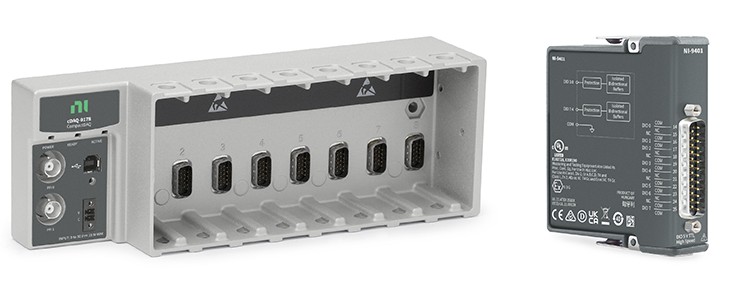
Many devices with hardware timing may be appropriate for counter measurements. Consider an NI CompactDAQ system as an example (see Figure 6). The hardware timebase for NI CompactDAQ is located on the backplane of the chassis and is not specific to the NI C Series modules themselves.
Figure 6. NI cDAQ-9178 Chassis and NI 9401 Digital I/O Module
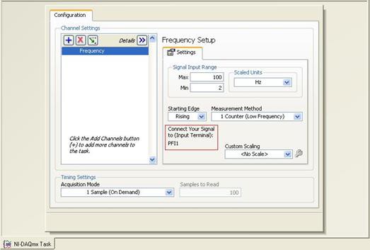
The NI 9401 has a D-Sub connector that provides connections for the eight digital channels. Each channel has a digital I/O pin to which you can connect a digital input or output device. Access to the four counters of the CompactDAQ chassis is available any of the slots of the chassis. After setting up the frequency acquisition as a counter task in Measurement & Automation Explorer (MAX), the PFI input terminal to which you should connect your signal is indicated (see Figure 7).
Figure 7. Screenshot of Configuration in Measurement & Automation Explorer (MAX)
Getting to See Your Measurements: NI LabVIEW
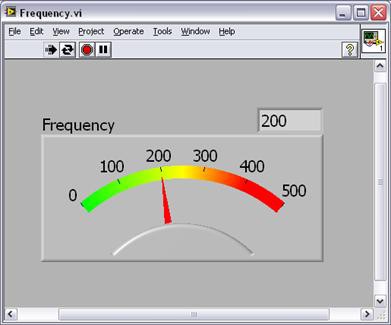
Once you have configured the system, you can view the data using the LabVIEW graphical programming environment (see Figure 8).
Figure 8. Frequency Measurement as Seen in LabVIEW
Recommended Hardware and Software
Frequency Webcasts Tutorials, and Other How-To Resources
- Making Accurate Frequency Measurements
- Learn About Relevant Training Options: Data Acquisition and Signal Conditioning
- Choosing a Counter Frequency Measurement Method for an NI DAQ Device
- How can I determine frequency error and frequency measurement or generation accuracy?
- Synchronizing Analog Input and Counter Frequency Measurements
- Maximum Frequency Measurement for NI Data Acquisition Devices


