RF Connector Care with NI Test Equipment
Overview
Contents
- Preventive Connector Care
- Proper Use of Connectors and Test Equipment
- Care and Maintenance of Adapters and Cables
- Cleaning Connectors
- Properly Torquing Connections
- Preventative Maintenance
- Connector Grades
Preventive Connector Care
Prior to using equipment, abide by the following practices to increase the life of the connectors and test equipment.
- Save dust covers and replace them on the appropriate connectors when test equipment is not in use. Products with coaxial connectors are shipped with dust covers to prevent contaminants from degrading connections.
- Store coaxial connectors in an ESD safe bin. While adapters and cables are not ESD sensitive, they can develop a charge that can be transferred to test equipment. Using an ESD safe bin will help reduce the possibility of charge transfer. Also the amount of non-ESD material near the equipment is reduced.
Proper Use of Connectors and Test Equipment
The first stage of making a good high frequency measurement involves a device front panel connector and the connections made to it. Many times, you use the most accessible cables and connectors to make connections to instruments, and usually this results in a reliable measurement. However, every adapter, connector, and cable that exists between the instrument and the DUT adds uncertainty to the measurement. At higher frequencies or frequencies closer to noise, those uncertainties have a larger impact on measurements. Reducing uncertainty begins with proper adapter and cable selection.
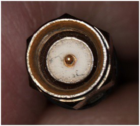
Be attentive when selecting cables and adapters. Verify the integrity of the equipment selected. Cable integrity can be degraded due to age, improper use, or contaminants. Contaminants from cables and adapters are easily transferred to the input connector of the test equipment. Figure 1 shows an example of a contaminated cable
Figure 1: Contaminated SMA Cable
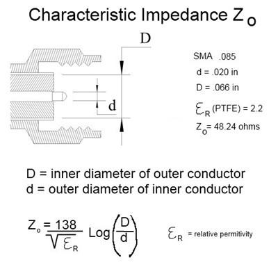
All of the metal fibers shown in Figure 1 are sources of uncertainty in measurements. Although the fibers may not contaminate any connector they interface with, they are very abrasive and can generate more contaminants as well as getting ground into the mating surfaces of both connectors. Using a connector with contaminants at low frequencies may not cause a problem, but using a connector with contaminants at high frequencies prevents a good match. The quality of the measurement is dependent on the match throughout the measurement system, which is dependent on the characteristic impedance of the various components. The characteristic impedance of the cable is dependent on the ratio of the diameter of the center conductor to the diameter of the outer conductor, as illustrated in Figure 2.
Figure 2: Characteristic Impedance of a Connector
Based on the preceding equation in Figure 2, little metal fibers act to decrease the diameter of the outer conductor, and this causes discontinuities in high frequency measurements.
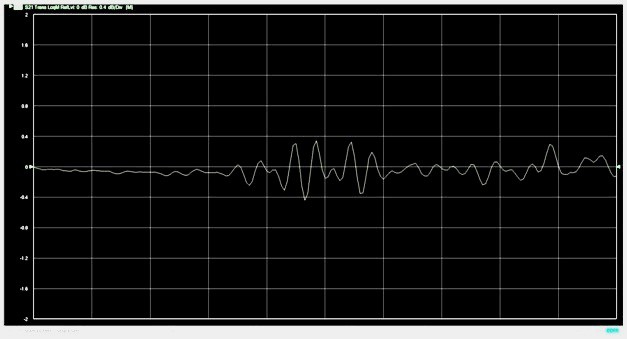
Figures 3 and 4 show an example of how discontinuities can negatively affect high frequency measurements.
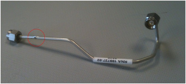
Figure 3 illustrates a 50 ohm coaxial semi-rigid cable measured on a network analyzer. Figure 4 shows the frequency response of the cable up to about 6 GHz.
Figure 3: Cable with Multiple Bends and an Intentional Crimp
Figure 4: Frequency Response of Cable Due to Bends Only
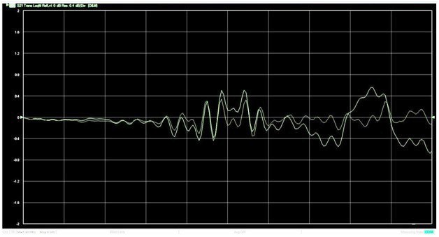
The cable was intentionally crimped near the connector (circled in red). Figure 5 shows the response of the cable with the crimp compared to the original cable with no crimp. The big discontinuity and the degradation in performance are caused by that crimp, which effectively moves the outer conductor closer to the inner conductor and changes the characteristic impedance. The effect is not limited to just a small portion of the measurement, but its effects can be seen across the full span of the measurement.
Figure 5: Frequency Response of Cable Due to Bends and Crimp
When the connector interface is contaminated, degradation in performance happens to a lesser degree.
Here are a few points to consider regarding cables and connector care:
- Contaminants follow the connector
- Contaminants “infect” mating connectors
- Contaminants can cause damage to expensive equipment
- Contaminants can cause discontinuities at high frequencies
- Good connections are key to precision RF measurements
- Dirty or damaged connectors are a significant factor in accuracy and repeatability
Care and Maintenance of Adapters and Cables
Despite taking all precautions, adapters and cables can become dirty. In those cases, cleaning will be necessary. Use the steps in the following section as a general guideline for cleaning connectors and cables.
Cleaning Connectors
The following materials are required for proper connector cleaning:
- Clean, dry source of canned air or nitrogen
- Magnifying glass
- Lint free swabs
- Isopropyl alcohol
- Toothpick
- Blow out any loose debris with canned air or nitrogen. Do not blow directly into the connector as this can cause debris to get lodged more firmly. Blow across the connector face. Using a compressor is not recommended but if necessary, verify that the compressor has a water filter, an oil filter, and a dryer. Always wear protective eyewear when using compressed air whether from a can or a compressor. Compressed air is the safest method for cleaning connectors with air dielectrics.
- Examine the connector with a magnifying glass. If you still notice debris, try removing it with a lint free, foam-tipped swab (not cotton). Cotton swabs leave fibers behind that are very hard to see. Use the swab to gently wipe the surfaces. Applying too much pressure can embed debris deeper into the connector. Do not perform this step on connectors with an air dielectric.
Note: When using a swab, always clean the connector in a circular motion around the center pin, not across the pin) - Examine the connector again, and if cleaning is still required, try using a foam swab with 99.5% isopropyl alcohol within a well ventilated area. Apply a very small amount of alcohol to the swab; do not apply the alcohol directly to the connector. Use the swab to gently wipe the surface. Do not perform this step on connectors with an air dielectric.
- Note: When using a swab, always clean the connector in a circular motion around the center pin, not across the pin.
Examine the connector again, and if the connector is still contaminated, it may be necessary to use a very small toothpick with a small amount of alcohol applied. Use a magnifier when using a toothpick to clean, and apply extreme care to avoid damaging the connector.
If you are not successful in cleaning the connector after completing the preceding steps, do not use that connector.
Properly Torquing Connections
Always use a torque wrench with the correct setting for the connector type being used. Too much torque can cause the mating surfaces to deform, which can result in a mismatch. Insufficient torque can give a bad connection also resulting in a mismatch. Always torque connections to the recommended torque value. Using a torque wrench will improve repeatability of your measurements.
Table 1: Recommended Torque Values
| Connector type | Torque in • lbs (N • cm) |
|---|---|
| SMA (brass & stainless) | 5 to 9 (56 to 100) |
| Precision 3.5 mm | 8 (90) |
| K connector (2.92) | 8 (90) |
| Type-N (stainless) | 12 to 15 (135 to 170) |
Complete the following steps to properly use a calibrated SMA torque wrench
- Fit the wrench around the connector hex nut, and apply force on the torque wrench using a smooth, steady action.
Caution: Do not apply force by holding any part of the wrench handle outside of the green zone, as shown in Figure 6, and do not use any other lever aid on the wrench. - Stop applying force any time after the break point and prior to reaching a 45 degree angle. Do not apply force after the wrench "breaks" at the preset torque, as indicated when the wrench leaves a linear position and begins to rotate separately from the wrench head. Do not apply force past 45 degrees, as indicated in Figure 6.
- If you over torque the connector, as indicated by the wrench completely breaking free (to 90 degrees or more from the wrench head), loosen the connector and repeat the operation. Pay special attention to the break point and stop tightening prior to reaching the maximum rotation angle.
The following figure illustrates how to properly grip the wrench to achieve the preset torque.
Figure 6: Proper Torque Wrench Use
Preventative Maintenance
The following information includes important tips for improving measurement techniques and measurements in general.
- Ensure that the male center pin on connectors aligns with the mating connector. During the cleaning process, inspect the mating surfaces on all connectors and cables before mating them. Look for any bent or damaged center pins or collets. Before mating connectors or cables, verify that the connector ends match and will mate without damage.
- After cleaning and inspecting cables and adapters, never turn the cable or body. Always turn only the connector nut. Turning the body instead of the nut causes the mating surfaces to wear down and become loose, causing a mismatch and degradation in measurements. Also the turning motion of the surfaces can cause burrs and loose metal shavings that not only affect the measurement but can damage any other surfaces they come in contact with.
- Using a connector saver does just what its name implies, it saves connectors. In a production or manufacturing environment where cables and connectors are frequently changed, a connector saver will increase the life of a piece of test equipment. As long as the effects of the connector saver are included in the error budget for a measurement, they pose little problem. Note that in a lab environment where many times the measurement requires a high degree of accuracy and care when making connections, the connector saver may not be the best choice.
Connector Grades
Three types of connectors are typically used, including metrology grade, instrument grade, and production grade (sometimes called field grade) connectors.
The metrology grade connector is the highest, most expensive grade of connector and is used on such items as verification and calibration standards and precision adapters. These connectors generally have slotless contacts and an air dielectric, and they are manufactured to the highest standards. When mated with other metrology grade standards, metrology grade connectors generally have a long life due to the precision mating characteristics. However, this does not make them more robust. Generally they are just the opposite and must be treated with much care.
The next grade down is the instrument grade connector. Instrument grade connectors are characterized by good performance with tight tolerances, and they often have a dielectric support structure. This is normally the type of connector used on most test equipment. Instrument grade connectors are more economical than the metrology grade connectors, but they still yield good performance.
The lowest grade of connector is the production grade or field grade connector. The production grade connectors generally have lower performance with looser tolerances and are therefore usually good only for a limited number of connections. These devices will almost always have a dielectric supported interface, and the female connector will almost always be of the slotted type. Production grade connectors should always be carefully inspected before connection. The production grade connector is usually very low cost (compared to the other grades) and has a short lifetime because the looser tolerances lead to a less precise fit and more wear.
