Understanding and Trusting Isolation Specifications
Overview
Contents
- The Need for Isolation Specifications
- Definitions
- Trusting Isolation Specifications
- Isolation Options in NI Hardware Products
- The Importance of Isolation
- Next Steps
The Need for Isolation Specifications
Isolation specifications are often overlooked but that doesn’t diminish their necessity in many applications. Isolation, specifically channel-to-earth ground isolation, is important for three reasons: signal integrity, safety, and instrument protection. Without detailed specifications, the only thing that isolation can tell you is whether ground loops will be broken, giving you better signal integrity. While this information is important, you should also look for a common-mode rejection ratio (CMRR) to earth ground to improve your signal integrity. CMRR details how well the device can reject common-mode signals or unwanted voltages that are common to both input terminals. Devices with isolation not only reject ground loops but also improve signal integrity by having a higher CMRR to earth ground.
For more information on isolation and measurement quality, see Isolation Technologies for Reliable Industrial Measurements.
According to Electrical Safety Foundation International, electrical hazards cause more than 300 deaths and 4,000 injuries per year. Isolation specifications can play an important role when dealing with safety and avoiding accidents. It can be used to separate high-voltage circuits from safety extra-low voltage (SELV) or user-touchable circuits. Especially in the case where the entire system is ungrounded, isolation helps prevent the SELV circuits from becoming energized when hazardous voltages are placed on the device. Because it would be impossible to ensure safety for every voltage level, isolation specifications can help you to specify the situations and how much voltage is safe to use with the device. This includes what voltages are safe and the measurement category of the voltage.
Finally, you can use isolation to protect your instrumentation when taking measurements with high common-mode voltages present. The range of an instrument is bounded by its amplifiers and converters, which are bounded by their power supplies and references, which are attached to the local ground. For a non-isolated instrument, the local ground is the system/earth ground. So the devices input range is in a window around earth ground. However, in an instrument with channel-to-earth isolation, the instrument’s local ground is not attached to earth ground. An isolated instrument therefore has a measurement range that is in a window around its isolated-local ground, which could float at a much different voltage than earth ground.
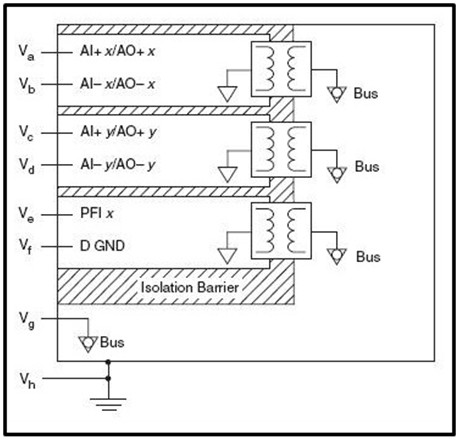
For a device with channel-to-channel and channel-to-earth isolation, this means that each channel has its own local ground that can float free of both earth ground and the other channels. This can allow the measurement of several tiny mV signals such as thermocouples each sitting at its own unique common-mode voltage. For example, when measuring temperatures of cells in an electric vehicle’s battery stack, a thermocouple instrument might have an input range of only 100 mV, but channel-to-channel isolation would permit each thermocouple to sit on top of the incremental 3.5 V per cell. The limit to how high the common voltages could go (or how many consecutive cells you could measure with that instrument) is then limited not by the input ranges of the amplifiers nor by the power supplies, but rather by the channel-to-earth ground or channel-to-channel isolation voltage (which is usually larger than the input range).
Figure 1: Channel-to-Earth Ground Isolation With Channel-to-Channel Isolation
As with safety, it would be impossible to create a device that could withstand unlimited common-mode voltage. Therefore it is critical that detailed isolation specifications be given to understand how much common-mode voltage your system can handle. These specifications give you the ability to know what window your device can measure in and, in turn, help you to avoid error and potential instrument damage.
Definitions
Isolation specifications are often difficult to understand. Below are several definitions to help you better understand how to interpret the specifications and apply them to your applications.
- Galvanic or Electrical Isolation—Galvanic or electrical isolation are redundant terms used in industry to market isolation. There are no fundamental differences between galvanic or electrical isolation and isolation. In measurement devices, they all mean that there is no direct electrical connection between circuits.
- Common-Mode Voltage—This is the voltage that is common to both measurement terminals. It can be a static DC offset such as a battery or appear as an AC signal such as ground noise.
- Working Voltage—This voltage can be continuously placed on the device. That is, the voltage measured plus common-mode voltage.
- Withstand Voltage—Withstand voltage is the amount of voltage the device can withstand for a brief period of time without damaging the system.
- Overvoltage Protection—This is the maximum voltage differential that can be sustained between a channel’s input terminals without damaging the input circuitry.
- Measurement Category—The Measurement Category is a rating for the environment that the measurement device will be placed in. It accounts for the transients the device might see considering where it is connected in the power distribution system.
- Pollution Degree—The Pollution Degree is another environmental rating that accounts for the amount of dry pollution and condensation that a device can handle while functioning properly. For more information on Pollution Degree, see Pollution Degree Rating for Electrical Equipment.
- Safety Voltage—This is the amount of voltage that can be applied between specified pins without creating a safety hazard.
- Safety Isolation—Insulation against hazardous voltages (UL defines these as over 60 VDC or 30 Vrms). This requires two layers of fault protection which usually results in either basic insulation with earth grounding of touchable surfaces or double/reinforced insulation.
- Functional Isolation—This is the amount of insulation needed only for the correct operation of the product.
Trusting Isolation Specifications
After you make sure the measurement device matches all of the isolation specifications that you need, the next step is to confirm those specifications are certified to meet safety standards. When dealing with safety, a “take our word for it” attitude cannot be tolerated. You must make sure that the product is properly certified. A product can have multiple levels of certification, including:
- CE Certification

The European Conformity (CE) marking is affixed to products with input of 50–1,000 Vac or 75–1,500 Vdc and/or for products that may cause or be affected by electromagnetic disturbance. The CE marking symbolizes that the products conform to the applicable Community requirements. CE is the manufacturer’s or supplier’s self-declaration allowing products to circulate freely within the Community. It is important to note that this is a self declaration that the product meets appropriate EMC and safety standards. For instance, National Instruments products that bear this mark meet the essential requirements of Directives 2004/108/EC (EMC) and 2006/95/EC (product safety), and comply with the relevant standards. Standards for measurement, control, and laboratory equipment include EN 61326 and EN 55011 for EMC and EN 61010-1 for product safety. - UL—North American Product Safety Certification or Equivalent


Underwriters Laboratories (UL) is an independent product safety testing and certification organization. The UL mark on a product means that it has been tested by UL and determined to meet UL requirements. Products are also periodically checked at the manufacturer’s facility. For example, the mark on National Instruments products indicates compliance with US (UL) and Canadian (CSA) safety standards, such as UL 61010-1 and CSA 61010-1.When an independent organization certifies the equipment, an extra layer of redundancy builds your confidence in the products ability to conform to safety standards. There are many equivalent organizations in Europe, a few examples are Demko and VDE. - UL—North American Hazardous Locations Certification or Equivalent

UL certifies products for use in hazardous locations where explosive atmospheres may be present. This certification has different levels of hazardous locations so make sure that the product complies with the location you are placing it in.
The European equivalent of a HAZLOC Certification is the Ex Mark from ATEX.
NI provides an easy way for you to find all of the certifications for our hardware products. Visit the Products Certification section of ni.com to find the certifications for a specific model.
Isolation Options in NI Hardware Products
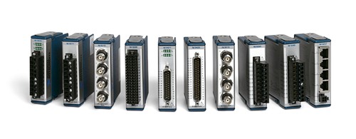
Figure 2 - The Majority of NI C Series Modules Offer Isolation with No Direct Electrical Connection Between Circuits
National Instruments takes safety and isolation specifications and certifications seriously. NI hardware is independently certified to be safe when used within specifications. The majority of the modules feature hazardous location certifications and/or isolation. For your convenience, NI has designed specific isolation levels that most modules fit into. This allows for uniformity across the platform while eliminating potential points of confusion. The isolation levels include the following listed below.
No Isolation
Only a few C Series I/O modules do not feature any isolation, for example the NI-9381 and NI-9234. Among other data acquisition products, the PXI strain/bridge module and dynamic signal acquisition devices are not isolated. These modules are still extremely safe and provide accurate measurements, but care should be taken to input only the appropriate signals specified in the manual and connect them properly.
60 VDC Continuous/1,000 Vrms Withstand
Over 25 module and connector variants feature 60 VDC continuous Category I and 1,000 Vrms withstand isolation between the channels and earth ground. Some of those modules also feature channel-to-channel isolation that provides 60 VDC between channels. Examples of modules with this level of isolation are:
- NI-9237 Four-Channel, ±25 mV/V, 24-Bit Simultaneous Bridge Module (Ch-Earth Ground Isolation)
- NI-9223 Four-Channel, 1 MS/s, 16-Bit Simultaneous Analog Input Module (Ch-Earth Ground and Ch-Ch Isolation)
- NI-9401 Eight-Channel, 5 V/TTL High-Speed Bidirectional Digital I/O Module (Ch-Earth Ground Isolation)
- PXIe-4357 Twenty-Channel RTD Input Module, 24-Bit Resolution (Ch-Earth Ground Isolation)
See all C Series Strain/Bridge Module, C Series Voltage Input Module, C Series Digital Module and PXI Temperature Input Module options.
250 Vrms Continuous/2,300 Vrms Withstand
Over 20 module and connector variants feature 250 Vrms continuous Category II and 2,300 Vrms withstand isolation between the channels and earth ground. Some of those modules also feature channel-to-channel isolation that provides 250 Vrms and 1,390 Vrms between channels. Examples of modules with this level of isolation are:
- NI-9219 Four-Channel, 24-Bit Universal Analog Input Module (Ch-Earth Ground and Ch-Ch Isolation)
- NI-9263 Four-Channel, 100 kS/s, 16-Bit, ±10 V, Analog Output Module (Ch-Earth Ground Isolation)
See all C Series Universal Analog Input Module and C Series Voltage Output Module options.
300 Vrms Continuous/2,300 Vrms Withstand
Several modules also feature 300Vrms CAT II continuous isolation between channels or between channels and earth ground.
- PXIe-4300 Eight-Channel, ±300V Simultaneous Analog Input Module (Ch-Ch and Ch-Earth Ground Isolation)
- PXIe-4353 Thirty-Two Channel Thermocouple Input Module, 24-Bit Resolution (Ch-Earth Ground Isolation)
- PXIe-4322 Eight Channel, ±16V, ±20mA Voltage and Current Output (Ch-Ch and Ch-Earth Ground Isolation)
See all PXI Analog Input Module, PXI Temperature Input Module and PXI Analog Output Module options.
600 VDC/300 Vrms Continuous/2,500 Vpk Rated Transient Overvoltage
Features 600 VDC/300Vrms CAT II continuous isolation between channels or between channels and earth ground.
- PXIe-4310 Eight-Channel, ±600V Simultaneous Analog Input Module (Ch-Ch and Ch-Earth Ground Isolation)
See all PXI Analog Input Module options.
Note: There are exceptions to the rules stated above, so it is important to check the isolation levels in the user manual.
The Importance of Isolation
Isolation is an important specification that is often overlooked. It can play a significant role in signal integrity, safety, and instrument protection. Whenever you buy a piece of measurement equipment, make sure that the device has the specifications that you need and that the specifications have been independently certified for safety.
Next Steps
- Find out more about the C Series Platform for control and monitoring applications with NI CompactRIO
- Find out more about the C Series Platform for data acquisition applications with NI CompactDAQ
- Learn more about specifications for Multifunction I/O (MIO) DAQ.
- Learn more about specifications for CompactDAQ and CompactRIO chassis and controllers


