From Saturday, Nov 23rd 7:00 PM CST - Sunday, Nov 24th 7:45 AM CST, ni.com will undergo system upgrades that may result in temporary service interruption.
We appreciate your patience as we improve our online experience.
From Saturday, Nov 23rd 7:00 PM CST - Sunday, Nov 24th 7:45 AM CST, ni.com will undergo system upgrades that may result in temporary service interruption.
We appreciate your patience as we improve our online experience.
Let's discuss the basic fundamentals of analog circuits. We'll discuss Ohm's law and basic analog circuit concepts as well as how to make various calculations.
The current (I) through the resistor (R) is defined as:
For a 1 Megaohm resistance, the current resulting from the application of 10 Volts would be 10 microamperes.
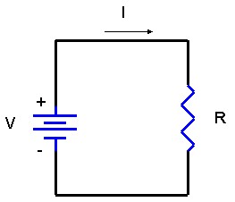
Ohm’s law is the fundamental equation that describes the above relationship between the voltage potential, the current flowing in the circuit, and the resistance of a circuit. The power dissipated in a load resistance (R) is defined as the product of the current and the voltage. Other relationships for power can be easily derived from this by applying Ohm’s law using substitution.
The power (P) dissipated in (R) is defined as:
To calculate the value of resistance that will result in 10 Watts with 10 Volts applied to it, we remember that P = V2/R. Transposing, R = V2/P. The resistance is 100/10, or 10 ohms. So 10V applied to 10 ohms will yield 10 Watts. Any time two of the parameters (V, R, or P) are numerically the same, the third one will be the same. A common way to measure resistance is by using a Digital Multimeter (DMM).
Note:The power dissipation (P) is what sets the limit for how much voltage can be applied to the 50 ohm input of a digitizer. From the equations, we see that 10 Volts into 50 ohms will require the digitizer’s input load to dissipate 2 Watts. If you are running 2 channels, that’s 4 Watts. This amount of power dissipation is definitely something that can’t be ignored. Also notice that because of the square law effect, if you double that voltage into the digitizer, the power it must dissipate will QUADRUPLE.
Voltage Divider Calculation:
When two resistors are connected in a series configuration, they must share the applied voltage and the same current flows through both of them.
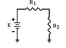
The formula used to calculate the applied voltage is:
(E1 = Voltage drop across R1)
(E2 = Voltage drop across R2)
To calculate the voltage across R2:
Note: Voltage divider is described by the equation above.
Current Divider Calculation:
When two resistors are connected in parallel configuration, the same voltage is across each of them. The amount of current flowing through them depends on the value of the resistances.
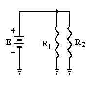
The above figure depicts two resistors in a parallel configuration.
Note: Digital multimeters (DMMs) are the most common measurement devices found in automated test systems. DMMs are usually simple to use and are often low-cost instruments. Generally, DMMs have built-in conditioning that provides:
a) High resolution (commonly measured in digits)
b) Multiple measurements (volts, current, resistance, etc)
c) Isolation and high voltage capabilities.
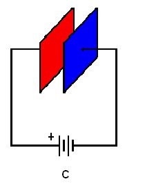
Capacitors store energy in the form of electrical charge. Amount of charge that the capacitor can hold depends on the area of the two plates in the figure above and the distance between them. Large plates with a small distance between them have a higher capacity to hold charge. The electric field between the plates of a capacitor resists changes in applied voltage. Capacitors decrease their resistance with frequency.
Reading Capacitor Values:
The unit of capacitance is Farad which is represented by the letter F. The formula to calculate capacitance is:
Where,
C = Capacitance in farads
Q = Accumulated Charge in Coulombs
V = Voltage difference between the plates
Series configuration:
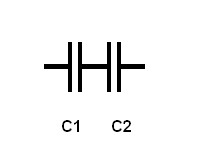
The above configuration represents two capacitors in series.
Since the capacitance of a capacitor is inversely proportional to the distance between the plates, the total capacitance CT of any number of capacitances can be calculated by the following:
For two capacitors connected in series,
Parallel Configuration:
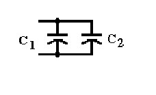
Each capacitor charges to the same applied voltage. Total capacitance equals the sum of the individual capacitances of the capacitors.
The formula used to calculate the capacitance is below:
Inductance is defined as the amount of voltage dropped across the inductor for a given rate of change of current flowing through it. Inductors increase their resistance with frequency. The unit of inductance is Henry which is represented by the letter H.
Series Configuration:
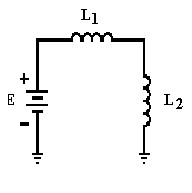
The Figure 7 above is a series configuration of two inductors.When two inductors are connected in series as shown above then their total inductance equals the sum of individual inductances.
Where dI/dt is the change of current over time.
However, in the real world if we consider mutual inductance where magnetic field of each inductor affects the other coil then the total inductance can be calculated using the formula below:
Where, M is the mutual inductance between the two coils.
Parallel Configuration:
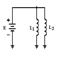
Figure 8 above is a parallel configuration of two inductors. When two inductors are connected in parallel configuration, mutual inductance needs to be considered. Also, mutual inductance will be either added or subtracted from the self-inductance of each coil since current has two paths to flow in.
The total inductance can be calculated using the formula below:
Impedance:
Impedance (Z) is generally defined as the total opposition a device or circuit offers to the flow of an alternating current AC at a given frequency. Its value is equal to the ratio between the voltage and the current over an element of a circuit. Therefore, the unit of impedance is ohm (Ω).
Impedance is represented as a complex quantity which is graphically shown on a vector plane. An impedance vector consists of a real part (resistance, R) and an imaginary part (reactance, X). Impedance can be expressed using the rectangular coordinate form R + jX or in the polar form as a magnitude and phase angle:
Z .
Admittance:
Admittance (Y) is the reciprocal of impedance. It is also a complex quantity: real part is called conductance (C) and the imaginary part is called susceptance (B).
The unit of admittance is siemens (S)
Y = G + jB
Where, Y is admittance; G represents conductance; and B represents susceptance.
Figure 9 below is a basic op-amp model that consists of three basic stages of an op-amp:
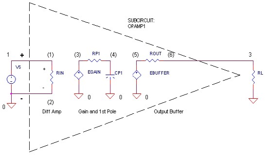
1) Differential Amplifier: An amplifier whose output is proportional to the difference between the input signals.
2) Gain/Frequency Response: A filter changes the amplitude or phase characteristics of a signal with respect to frequency. The frequency domain behavior of a filter is mathematically described in terms of a transfer function or a network function. The transfer function H(s) is described as a ratio between output and input signals.
Where, Vout(s) and Vin(s) are the output and input voltage signals and s is the complex frequency variable.
The magnitude of transfer function is called amplitude response or frequency response especially in radio applications.
3) Output Buffer
Inverting Amplifier: An Inverting is as simple as it sounds, it simply reverses the polarity of the input signal. For example, if the voltage going into the amplifier is positive, it is negative when it comes out.
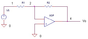
Calculating the gain of an inverting amplifier:
Since V1 = V = 0 (Virtual ground)
Non-Inverting Amplifier: The gain of the amplifer is determined by the ratio of R1 and R2.
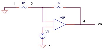
Calculating the gain of a non-inverting amplifier:
Where
Note: All the Data Acquisition (DAQ) products offered by National Instruments have built-in amplifiers.
RC Low Pass Filter: A common circuit to attenuate high-frequency components in an analog signal is the RC Low Pass Filter. Examine the diagram below, where Vin is the applied voltage and the voltage Vout across C1 is the output.
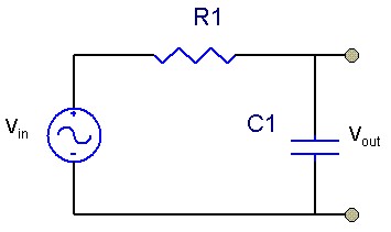
The RC Low Pass Filter passes low frequency and DC signals to the output, but blocks out high frequency signals. This could be either desirable or undesirable.
You get the equivalent of this circuit even when you do not expect it. For example, C could be the input capacitance of a Digital Multimeter(DMM), Digitizer, etc. R in this example might be the source resistance of the device under test (DUT). The DUT has to charge and discharge C as the signal varies. As the variation increases in frequency, the impedance of C eventually becomes lower than R and starts to attenuate the signal. The frequency where the value of Vout is at 0.707 of Vin, is defined as the –3dB frequency or the half-power point, because the output is down –3dB of the input signal at that point.
Single-Pole RC Low Pass
RC High Pass Filter: A circuit that attenuates low-frequency components in an analog signal is called a RC High Pass Filter. Notice that the circuit is similar to the one above, but Vout is now measured across R1.
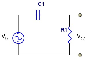
A very important typical application of this circuit is in the input coupling circuits of a Digitizer or Digital Multimeter (DMM). With the capacitor in, it is “AC Coupled.” With the capacitor shorted, it would be “DC Coupled.”
Note: Low pass and High pass filters are also used in Dynamic Signal Acquisition (DSA) devices