Testing Perception and Sensor Fusion Systems
Overview
An autonomous vehicle’s (AV) most computationally complex components lie within the perception and sensor fusion system. This system must make sense of the information that the sensors provide, which might include raw point-cloud and video-stream data. The perception and sensor fusion system’s job is to crunch all of the data and determine what it is seeing: Lane markings, pedestrians, cyclists, vehicles, or street signs, for example.
To address this computational challenge, automotive suppliers seemingly could build a supercomputer and throw it in the vehicle. However, a supercomputer consumes heaps of power, and that directly conflicts with the automotive industry’s goal to create efficient cars. We can’t expect Level 4 vehicles to be connected to a huge power supply to run the largest and smartest computer for making huge decisions. The industry must strike a balance between processing power and power consumption.
Such a monumental task requires specialized hardware; for example, “accelerators” that help specific algorithms that perceive the world execute extremely fast and precisely. Learn more about that hardware architecture and its various implementations in the next section. After that, discover methodologies to test the perception and sensor fusion systems from a hardware and system-level test perspective.
Contents
- Perception and Sensor Fusion Systems
- Semiconductor Hardware-Level Tests
- Compute-Platform Validation
- Embedded Software and Systems Tests
- Algorithm Design and Development
- Conclusion
Perception and Sensor Fusion Systems
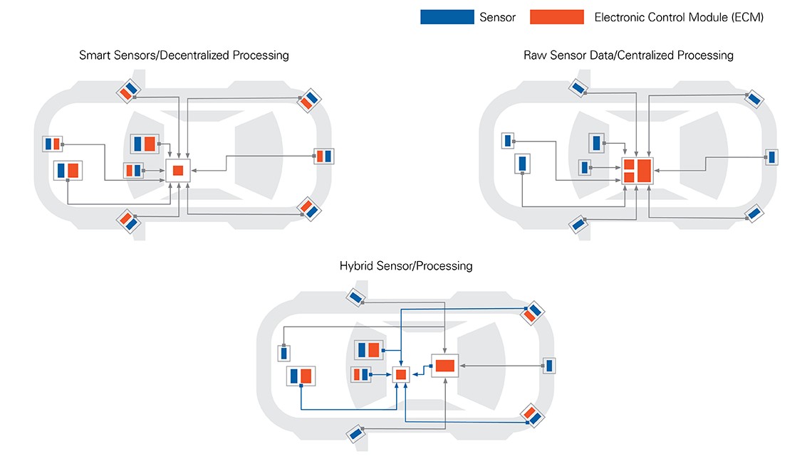
As noted in the introduction, AV brains can be centralized in a single system, distributed to the edge of the sensors, or a combination of both:
Figure 1: Control Placement Architectures
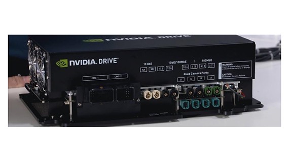
NI often refers to a centralized platform as the AV compute platform, though other companies have different names for it. AV compute platforms include the Tesla full self-driving platform and the NVIDIA DRIVE AGX platform.
Figure 2: NVIDIA DRIVE AGX Platform
MobilEye’s EyeQ4 offers decentralized sensors. If you combine such platforms with a centralized compute platform to offload processing, they become a hybrid system.
When we speak of perception and sensor fusion systems, we isolate the part of the AV compute platform that takes in sensor information from the cameras, RADARs, Lidars, and, occasionally, other sensors, and spits out a representation of the world around the vehicle to the next system: The path planning system. This system locates the vehicle in 3D space and maps it in the world..
Hardware and Software Technologies
Certain processing units are best-suited for certain types of computation; for example, CPUs are particularly good at utilizing off-the-shelf and open source code to execute high-level commands and handle memory allocation. Graphics processing units can handle general-purpose image processing very well. FPGAs are excellent at executing fixed-point math very quickly and deterministically. You can find tensor processing units and neural network (NN) accelerators built to execute deep learning algorithms with specific activation functions, such as rectified linear units, extremely quickly and inparallel. Redundancy is built into the system to ensure that, if any component fails, it has a backup.
Because backups are critical in any catastrophic failure, there cannot be a single point of failure (SPOF) anywhere, especially if those compute elements are to receive their ASIL-D certification.
Some of these processing units consume large amounts of power. The more power compute elements consume, the shorter the range of the vehicle (if electric), and the more heat that’s generated. That is why you’ll often find large fans on centralized AV compute platforms and power-management integrated circuits in the board. These are critical for keeping the platform operating under ideal conditions. Some platforms incorporate liquid cooling, which requires
controlling pumps and several additional chips.
Atop the processing units lies plenty of software in the form of firmware, OSs, middleware, and application software. As of this writing, most Level 4 vehicle compute platforms run something akin to the Robot Operating System (ROS) on a Linux Ubuntu or Unix distribution. Most of these implementations are nondeterministic, and engineers recognize that, in order to deploy safety critical vehicles, they must eventually adopt a real-time OS (RTOS). However, ROS and similar robot middleware are excellent prototyping environments due to their vast amount of open source tools, ease of getting started, massive online communities, and data workflow simplicity.
With advanced driver-assistance systems (ADAS), engineers have recognized the need for RTOSs and have been developing and creating their own hardware and OSs to provide it. In many cases, these compute-platform providers incorporate best practices such as the AUTOSAR framework.
Perception and sensor fusion system software architecture varies dramatically due to the number and type of sensors associated with the perception system; types of algorithms used; hardware that’s running the software; and platform maturity. One significant difference in software architecture is “late” versus “early” sensor fusion.
Product Design Cycle
To create a sensor fusion compute platform, engineers implement a multistep process. First, they purchase and/or design the chips. Autonomous compute platform providers may employ their own silicon design, particularly for specific NN accelerators. Those chips undergo test as described in the semiconductor section below. After the chips are confirmed good, contract manufacturers assemble and test the boards. Embedded chip software design and simulation occur in parallel to chip design and chip/module bring-up. Once the system is assembled, engineers conduct functional tests and embedded software tests, such as hardware-in-the-loop (HIL). Final compute-platform packaging takes place in-house or at the contract manufacturer, where additional testing occurs.
Semiconductor Hardware-Level Tests
As engineers design these compute units, they execute tests to ensure that the units operate as expected.:
Semiconductor-Level Validation and Verification
As mentioned, all semiconductor chips undergo a process of chip-level validation and verification. Typically, these help engineers create specifications documents and send the product through the certification process. Often, hardware redundancy and safety are checked at this level. Most of these tests are conducted digitally, though analog tests also ensure that the semiconductor manufacturing process occurred correctly.
Semiconductor-Level Production Test
After the chip engineering samples are verified, they’re sent into production. Several tests unique to processing units at the production wafer-level test stage revolve around testing the highly dense digital connections on the processors.
At this stage, ASIL-D and ISO 26262 validation occurs, and further testing confirms redundancy, identifies SPOF, and verifies manufacturing process integrity.
Compute-Platform Validation
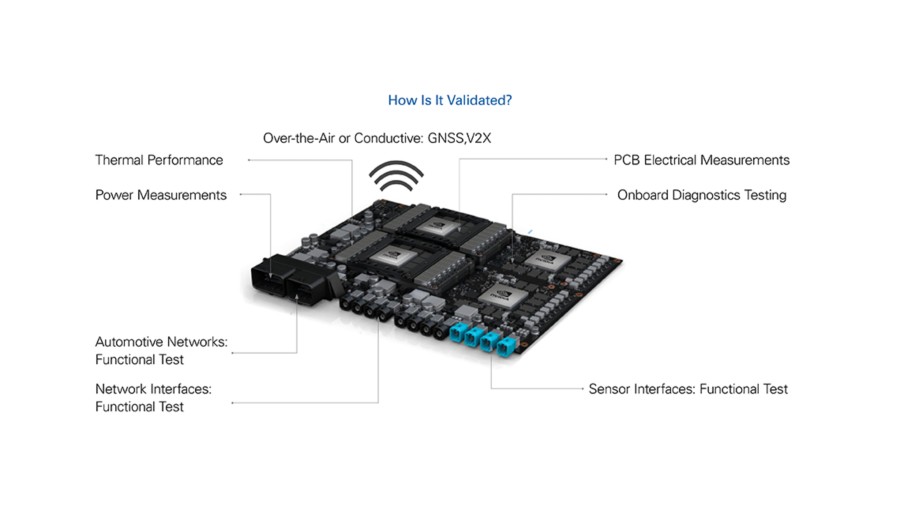
After compute-platform manufacturers receive their chips and package them onto a module or subsystem, the compute-platform validation begins. Often, this means testing various subsystem functionality and the entire compute platform as a whole; for example:
- Ensuring that all automotive network ports (controller area network [CAN], local interconnect network, and T1/Ethernet [ENET]) are communicating correctly in both directions
- Ensuring that all standard network ports (ENET, USB, and PCIe) are communicating correctly in both directions
- Ensuring that all sensor interfaces can communicate and handle standard loads for each type of sensor
- Providing a representative “load” on the system and validating that it completes a task
- Measuring the various element and complete system power consumptions as they
complete a task - Measuring system thermal performance under various loads
- Placing the subsystem or entire compute platform in a temperature, environmental, or accelerating (shaker table) chamber to ensure that it can withstand extreme operating conditions
- Verifying that the system can connect to a GPS or global navigation satellite system (GNSS) port and synchronizing it with the clock to a certain specification and within a certain time
- Checking onboard system diagnostics
- Power-cycling the complete system at various voltage and current levels
Figure 3: Chip Validation
Functional and Module-Level Test
Because the compute platform is a perfect mix of both consumer electronics components and automotive components, you have to thoroughly validate it with testing procedures from both industries: You need automotive and consumer electronics network interfaces and methodologies.
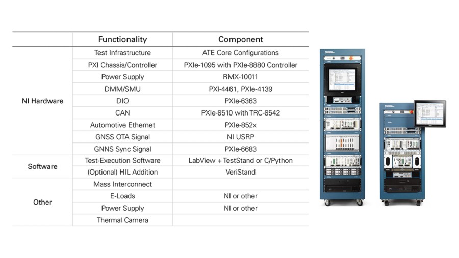
NI is uniquely suited to address these complex requirements through our Autonomous Compute Platform Validation product. We selected a mix of the interfaces and test instruments you might require to address the validation steps outlined above, and packaged them into a single configuration. Because we utilize PXI instrumentation, our flexible solution easily addresses changing and growing AV validation needs. Figure 4 shows a solution example:
Figure 4: Autonomous Compute Platform Validation Solution Example
Life Cycle, Environmental, and Reliability Tests
Functionally validating a single compute platform is fairly straightforward. However, once the scope of the test grows to encompass multiple devices at a time or in various environments, test system size and complexity grows. It’s important to incorporate functional test and scale the number of test resources appropriately, with corresponding parallelism or serial testing capabilities. Also, you need to integrate the appropriate chambers, ovens, shaker tables, and dust rooms to simulate environmental factors. And because some tests must run for days, weeks, or even months to represent the life cycle of the devices under test, tests need to execute—uninterrupted—for that duration of time.
All of these life cycle, environmental, and reliability testing challenges are solved with the right combination of test equipment, chambering, DUT knowledge, and integration capability. To learn more about our partner channel that can assist with integrating these complex test systems, please contact us.
Embedded Software and Systems Tests
Perception and sensor fusion systems are the most complex vehicular elements for both hardware and software. Because the embedded software in these systems is truly cutting-edge, software validation test processes also must be cutting-edge. Later in this document, learn more about isolating the software itself to validate the code as well as testing the software once it has been deployed onto the hardware that will eventually go in the vehicle.
Figure 5: Simulation, Test, and Data Recording
Algorithm Design and Development
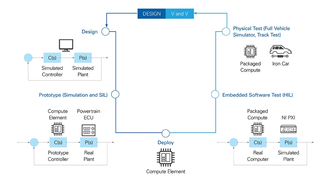
We can’t talk about software test without recognizing that the engineers and developers designing the software are constantly trying to improve their software’s capability. Without diving in too deeply, know that software that is appropriately architected makes validating that software significantly easier.
Figure 6: Design, Deployment, and Verification and Validation (V and V)
Software Test and Simulation
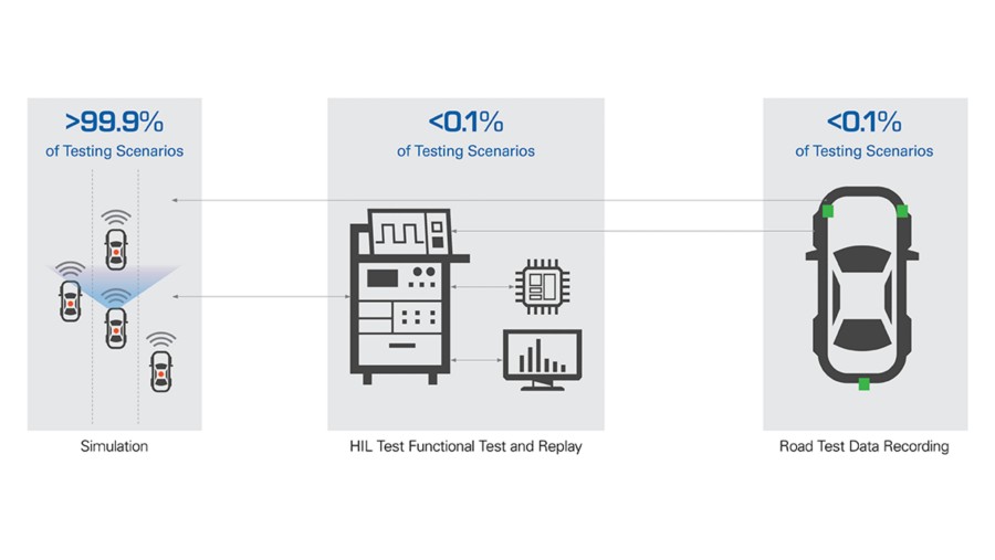
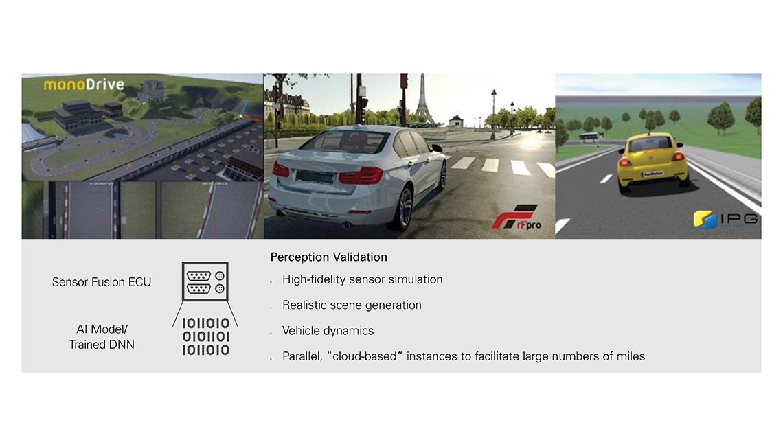
99.9% of perception and sensor fusion validation occurs in software. It’s the only way to test an extremely high volume within reasonable cost and timeframe constraints because you can utilize cloud-level deployments and run hundreds of simulations simultaneously. Often, this is known as simulation or software-in-the-loop (SIL) testing. As mentioned, we need an extremely realistic environment if we are testing the perception and sensor fusion software stack; otherwise, we will have validated our software against scenarios and visual representation that only exists in cartoon worlds.
Figure 7: Perception Validation Characteristics
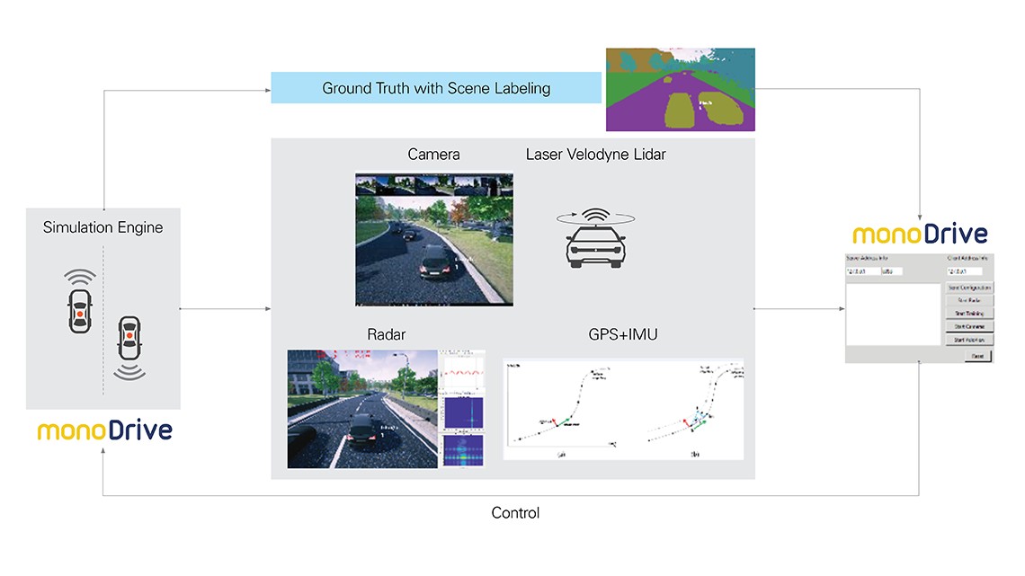
Testing AV software stack perception and sensor fusion elements requires a multitude of things: You need a representative “ego” vehicle in a representative environmental worldview. You need to place realistic sensor representations on the ego vehicle in spatially accurate locations, and they need to move with the vehicle. You need accurate ego vehicle and environmental physics and dynamics. You need physics-based sensor models that give you actual information that a realworld sensor would provide, not some idealistic version of it.
After you have equipped the ego vehicle and set up the worldview, you need to execute scenarios for that vehicle and sensors to encounter by playing through a preset or prerecorded scene. You also can let the vehicle drive itself through the scene. Either way, the sensors must have a communication link to the software under test. It can be through some type of TCP link—either running on the same machine or separately—to the software under test.
That software under test is then tasked with identifying its environment, and you can verify how well it did by comparing the results of the perception and sensor fusion stack against the “ground truth” that the simulation environment provides.
Figure 8: Testing Perception and Planning
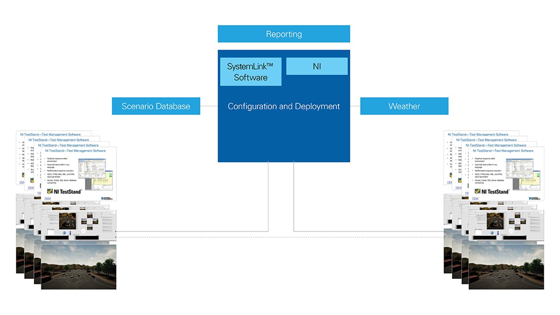
The real advantage is that you can spin up tens of thousands of simulation environments in the cloud and cover millions of miles per day in simulated test scenarios. To learn more about how to do this, contact us.
Figure 9: Using the Cloud with SystemLink Software
Record and Playback
If you live in a city that tests AVs, you may have seen those dressed-up cars navigating the road with test drivers hovering their hands over the wheel. Those mule vehicles rack up millions of miles so that engineers can verify their software. There are many steps to validating software with road-and-track test..
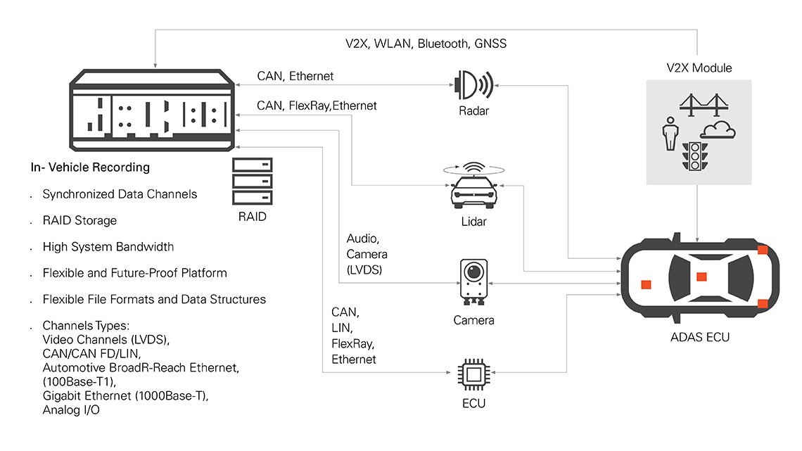
The most prevalent methodology for validating embedded software is to record a bunch of realworld sensor information through the sensors placed on vehicles. This is the highest-fidelity way to provide software-under-test sensor data, as it is actual, real-world data. The vehicle can be in autonomous mode or non autonomous mode. It is the engineer’s job to equip the vehicle with a recording system that stores massive amounts of sensor information without impeding the vehicle. A representative recording system is shown in Figure 10:
Figure 10: Figure 10. Vehicle Recording System
Once data records onto large data stores, it needs to move to a place where engineers can play with it. The process of moving the data from a large raid array to the cloud or on-premise storage is a challenge, because we’re talking about moving tens, if not hundreds, of terabytes to storage as quickly as possible. There are dedicated copy centers and server-farm-level interfaces that can help accomplish this.
Engineers then face the daunting task of classifying or labeling stored data. Typically, companies pay millions of dollars to send sensor data to buildings full of people that visually inspect the data and identify things such as pedestrians, cars, and lane markings. These identifications serve as “ground truth” for the next step of the process. Many companies are investing heavily in automated labeling that would ideally eliminate the need for human annotators, but that technology is not yet feasible. As you might imagine, sufficiently developing that technology would greatly reduce testing embedded software that classifies data, resulting in much more confidence in AVs.
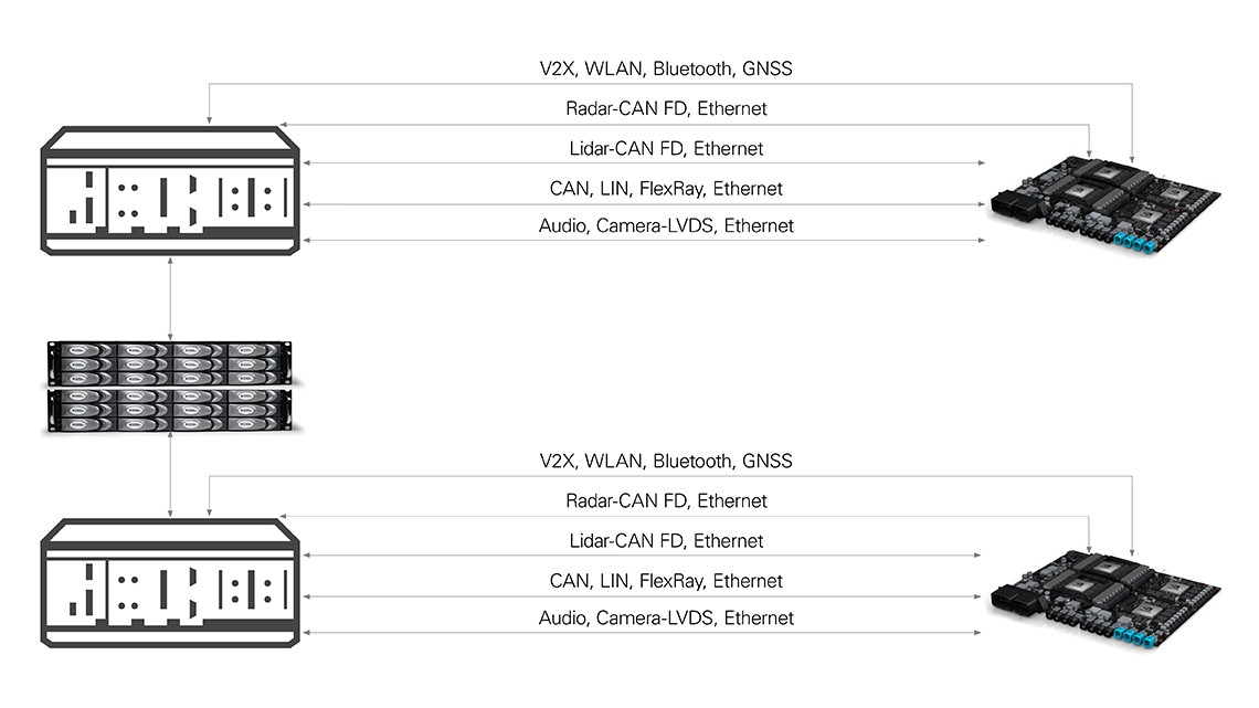
After data has been classified and is ready for use, engineers play it back into the embedded software, typically on a development machine (open-loop software test), or on the actual hardware (open-loop hardware test). This is known as open-loop playback because the embedded software is not able to control the vehicle—it can only identify what it sees, which is then compared against the ground truth data.
Figure 11: Figure 11. ADAS Data Playback Diagram
One of the more cutting-edge things engineers do is convert real-world sensor data into their simulation environment so that they can make changes to their prerecorded data. This way, they can add weather conditions that the recorded data didn’t see, or other scenarios that the recording vehicle didn’t encounter. While this provides high-fidelity sensor data and test-case breadth, it is quite complex to implement. It does provide limited capability to perform closedloop tests, such as SIL, with real-world data while controlling a simulated vehicle.
Mule vehicles equipped with recording systems are often very expensive and take significant time and energy to deploy and rack up miles. Plus, you can’t possibly encounter all of the various scenarios you need to validate vehicle software. This is why you see significantly more tests performed in simulation.
HIL Test
Once there’s an SIL workflow in place, it’s easier to transition to HIL, which runs the same tests with the software onboard the hardware that eventually makes it into the vehicle. You can take the existing SIL workflow and cut communication between the simulator and the software under test. And you can add an abstraction layer between the commands sent to and from the simulator and hardware that has sensor and network interfaces to communicate with the compute platform under test. The commands talking to the hardware must execute in real time to be validated appropriately. You can take those same sensor interfaces described in the AV Functional Test section and plug them into the SIL system with the real-time software abstraction layer and create a true HIL tester.
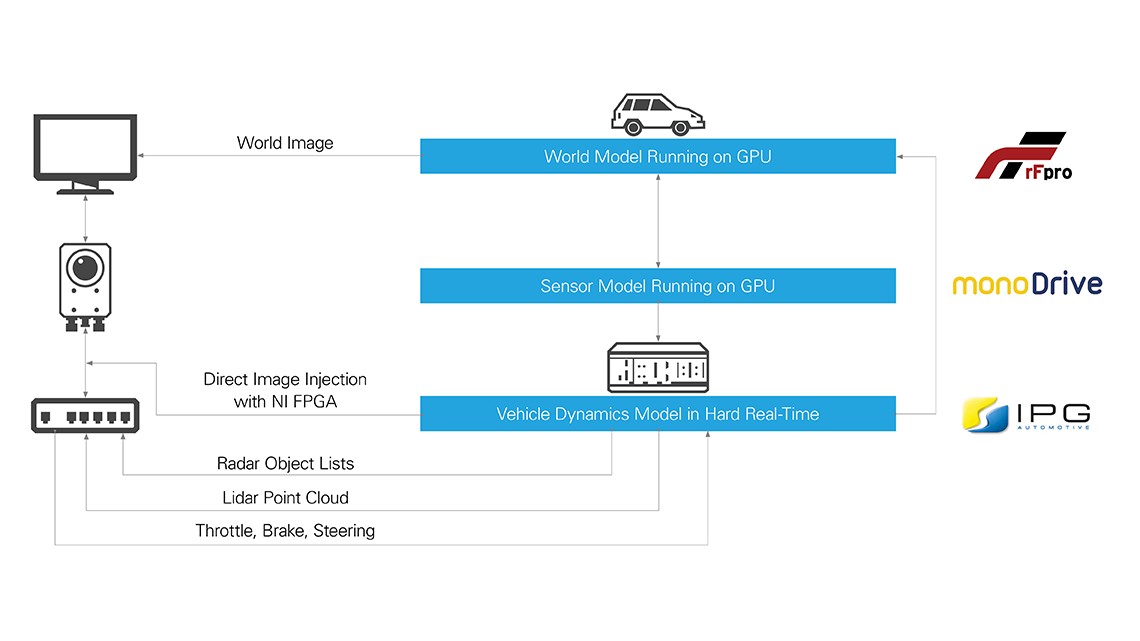
You can execute perception and sensor fusion HIL tests either by directly injecting into the sensor interfaces, or, with the sensor in the loop, providing an emulated over-the-air interface to the sensors, as shown in Figure 12.
Figure 12: Figure 12. Closed-Loop Perception Test
Each of these processes—from road test to SIL to HIL—employ a similar workflow. For more information about this simulation test platform, contact us.
Conclusion
Now that you understand how to test AV compute platform perception and sensor fusion systems, you may want a supercomputer as the brain of your AV. Know that, as a new market emerges, there are uncertainties. NI offers a software-defined platform that helps solve functional testing challenges to validate the custom computing platform and test automotive network protocols, computer protocols, sensor interfaces, power consumption, and pin measurements. Our platform flexibility, I/O breadth, and customizability cover not only today’s testing requirements to bring the AV to market, but can help you swiftly adapt to tomorrow’s needs.
LabVIEW, National Instruments, NI, NI TestStand, NI VeriStand, ni.com, and USRP are trademarks of National Instruments. Other product and company names listed are trademarks or trade names of their respective companies.
