LabVIEW Arrays and Clusters Explained
Overview
This article examines array and cluster data types and gives you an introduction to creating and manipulating arrays and clusters.
An array, which consists of elements and dimensions, is either a control or an indicator – it cannot contain a mixture of controls and indicators. Elements are the data or values contained in the array. A dimension is the length, height, or depth of an array. Arrays are very helpful when you are working with a collection of similar data and when you want to store a history of repetitive computations.
Array elements are ordered. Each element in an array has a corresponding index value, and you can use the array index to access a specific element in that array. In NI LabVIEW software, the array index is zero-based. This means that if a one-dimensional (1D) array contains n elements, the index range is from 0 to n – 1, where index 0 points to the first element in the array and index n – 1 points to the last element in the array.
Clusters group data elements of mixed types. An example of a cluster is the LabVIEW error cluster, which combines a Boolean value, a numeric value, and a string. A cluster is similar to a record or a struct in text-based programming languages.
Similar to arrays, a cluster is either a control or an indicator and cannot contain a mixture of controls and indicators. The difference between clusters and arrays is that a particular cluster has a fixed size, where a particular array can vary in size. Also, a cluster can contain mixed data types, but an array can contain only one data type.
Contents
Creating Array Controls and Indicators
To create an array in LabVIEW, you must place an array shell on the front panel and then place an element, such as a numeric, Boolean, or waveform control or indicator, inside the array shell.
- Create a new VI.
- Right-click on the front panel to display the Controls palette.
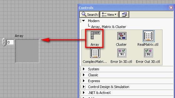
- On the Controls palette, navigate to Modern»Array, Matrix, & Cluster and drag the Array shell onto the front panel.
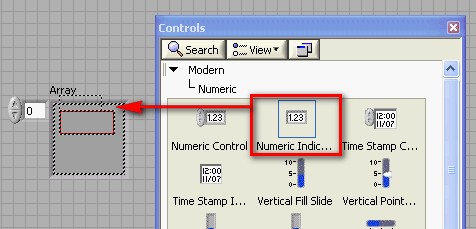
- On the Controls palette, navigate to Modern»Numeric and drag and drop a numeric indicator inside the Array shell.
- Place your mouse over the array and drag the right side of the array to expand it and display multiple elements.
The previous steps walked you through creating a 1D array. A 2D array stores elements in a grid or matrix. Each element in a 2D array has two corresponding index values, a row index and a column index. Again, as with a 1D array, the row and column indices of a 2D array are zero-based.
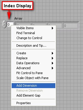
To create a 2D array, you must first create a 1D array and then add a dimension to it. Return to the 1D array you created earlier.
- On the front panel, right-click the index display and select Add Dimension from the shortcut menu.
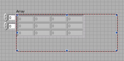
- Place your mouse over the array and drag the corner of the array to expand it and display multiple rows and columns.
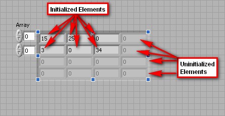
Up to this point, the numeric elements of the arrays you have created have been dimmed zeros. A dimmed array element indicates that the element is uninitialized. To initialize an element, click inside the element and replace the dimmed 0 with a number of your choice.
You can initialize elements to whatever value you choose. They do not have to be the same values as those shown above.
Creating Array Constants
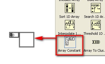
You can use array constants to store constant data or as a basis for comparison with another array.
- On the block diagram, right-click to display the Functions palette.
- On the Functions palette, navigate to Programming»Array and drag the Array Constant onto the block diagram.
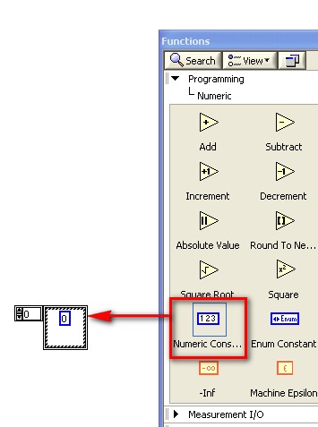
- On the Functions palette, navigate to Programming»Numeric and drag and drop the Numeric Constant inside the Array Constant shell.
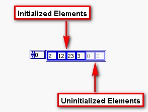
- Resize the array constant and initialize a few of the elements.
Array Inputs/Outputs
If you wire an array as an input to a for loop, LabVIEW provides the option to automatically set the count terminal of the for loop to the size of the array using the Auto-Indexing feature. You can enable or disable the Auto-Indexing option by right-clicking the loop tunnel wired to the array and selecting Enable Indexing (Disable Indexing).
If you enable Auto-Indexing, each iteration of the for loop is passed the corresponding element of the array.
When you wire a value as the output of a for loop, enabling Auto-Indexing outputs an array. The array is equal in size to the number of iterations executed by the for loop and contains the output values of the for loop.
- Create a new VI. Navigate to File»New VI.
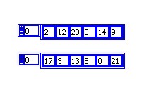
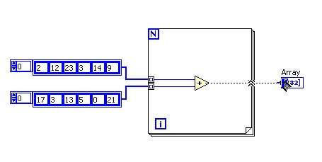
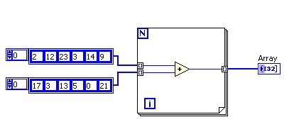
- Create and initialize two 1D array constants, containing six numeric elements, on the block diagram similar to the array constants shown below.
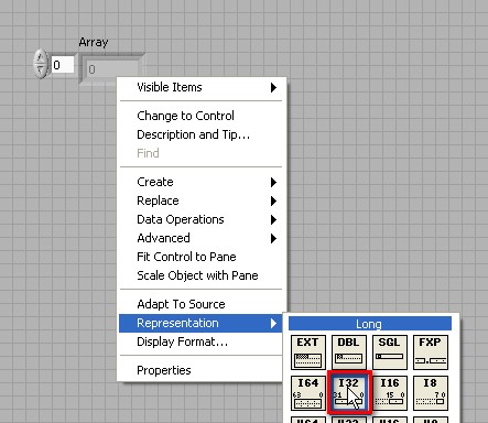
- Create a 1D array of numeric indicators on the front panel. Change the numeric type to a 32-bit integer. Right-click on the array and select Representation»I32.
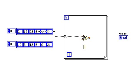
- Create a for loop on the block diagram and place an add function inside the for loop.
- Wire one of the array constants into the for loop and connect it to the x terminal of the add function.
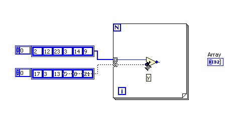
- Wire the other array constant into the for loop and connect it to the y terminal of the add function.
- Wire the output terminal of the add function outside the for loop and connect it to the input terminal of the array of numeric indicators.
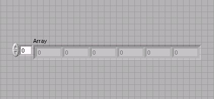
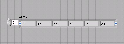
- Your final block diagram and front panel should be similar to those shown below.
Block Diagram
Front Panel
- Go to the front panel and run the VI. Note that each element in the array of numeric indicators is populated with the sum of the corresponding elements in the two array constants.
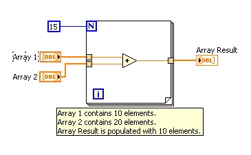
Be aware that if you enable Auto-Indexing on more than one loop tunnel and wire the for loop count terminal, the number of iterations is equal to the smaller of the choices. For example, in the figure below, the for loop count terminal is set to run 15 iterations, Array 1 contains 10 elements, and Array 2 contains 20 elements. If you run the VI in the figure below, the for loop executes 10 times and Array Result contains 10 elements. Try this and see it for yourself.
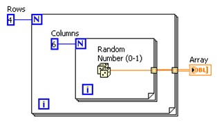
You can create a 2D array using nested for loops and Auto-Indexing as shown below. The outer for loop creates the row elements, and the inner for loop creates the column elements.
Creating Clusters
- Create a new VI.
- Right-click on the front panel to display the Controls palette.
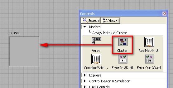
- On the Controls palette, navigate to Modern»Array, Matrix, & Cluster and drag the Cluster shell onto the front panel.
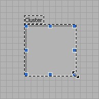
- Resize the Cluster shell so that it is big enough to contain multiple elements.
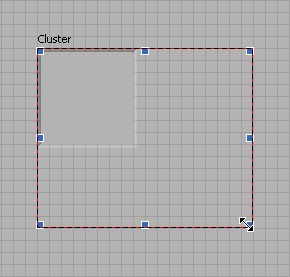
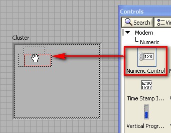
- On the Controls palette, navigate to Modern»Numeric and drag and drop a numeric control inside the Cluster shell.
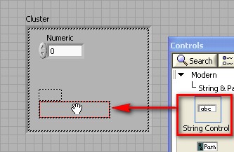
- On the Controls palette, navigate to Modern»String & Path and drag and drop a String Control inside the Cluster shell.
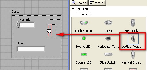
- On the Controls palette, navigate to Modern»Boolean and drag and drop a Vertical Toggle Switch inside the Cluster shell.
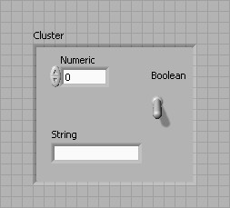
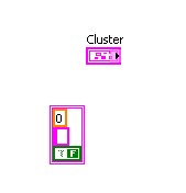
- Your cluster should now look similar to the one shown below.
You can now wire the numeric, string, and Boolean controls throughout the block diagram with one wire rather than three separate wires.
Creating Cluster Constants
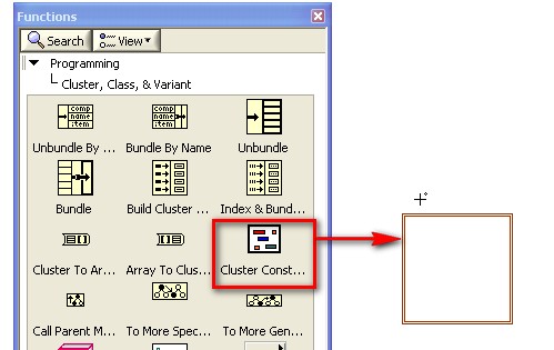
Similar to array constants, you can use cluster constants to store constant data or as a basis for comparison with another cluster. Create cluster constants the same way you created array constants in the steps discussed earlier.
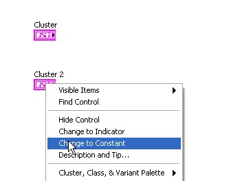
If you already have a cluster control or indicator and want to make a cluster constant that contains the same data types, make a copy of the cluster control or indicator on the block diagram and then right-click on the copy and select Change to Constant from the shortcut menu.
Cluster Functions
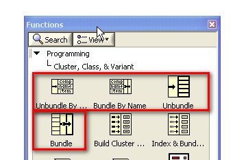
This tutorial examines four main cluster functions often used to manipulate clusters. These are the Bundle, Unbundle, Bundle By Name, and Unbundle By Name functions.
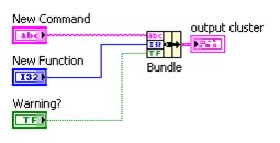
Use the Bundle function to assemble a cluster from individual elements. To wire elements into the Bundle function, use your mouse to resize the function or right-click on the function and select Add Input from the shortcut menu.
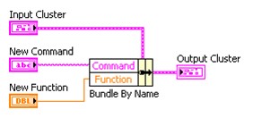
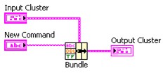
Use the Bundle By Name or the Bundle function to modify an existing cluster. You can resize the Bundle By Name function in the same manner as the Bundle function.
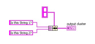
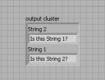
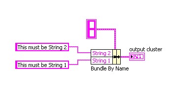
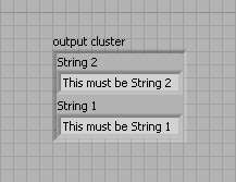
The Bundle By Name function is very useful when modifying existing clusters because it lets you know exactly which cluster element you are modifying. For example, consider a cluster that contains two string elements labeled “String 1” and “String 2.” If you use the Bundle function to modify the cluster, the function terminals appear in the form of pink abc’s. You do not know which terminal modifies “String 1” and which terminal modifies “String 2.”
However, if you use the Bundle By Name function to modify the cluster, the function terminals display the element label so that you know which terminal modifies “String 1” and which terminal modifies “String 2.”
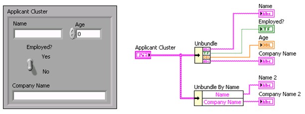
Use the Unbundle function to disassemble a cluster into its individual elements. Use the Unbundle by Name function to return specific cluster elements you specify by name. You can also resize these functions for multiple elements in the same manner as the Bundle and Bundle By Name functions.
Cluster Order
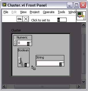
Cluster elements have a logical order unrelated to their position in the shell. The first object you place in the cluster is element 0, the second is element 1, and so on. If you delete an element, the order adjusts automatically. The cluster order determines the order in which the elements appear as terminals on the Bundle and Unbundle functions on the block diagram. You can view and modify the cluster order by right-clicking the cluster border and selecting Reorder Controls In Cluster from the shortcut menu.
The white box on each element shows its current place in the cluster order. The black box shows the element’s new place in the order. To set the order of a cluster element, enter the new order number in the Click to set to text box and click the element. The cluster order of the element changes, and the cluster order of other elements automatically adjusts. Save the changes by clicking the Confirm button on the toolbar. Revert to the original order by clicking the Cancel button.
