Linear Waveform Generation with CompactRIO and LabVIEW FPGA
Overview
Reconfigurable I/O (RIO) hardware from NI empower developers with the ability to create custom hardware to perform many tasks in a rugged, high-performance, and modular architecture without knowledge of low-level EDA tools or hardware design. One such task easily implemented with RIO hardware is analog waveform generation. This tutorial describes different methods that can be taken to output linear waveforms using CompactRIO hardware and the LabVIEW FPGA Module. For information on other types of waveform generation with the LabVIEW FPGA Module return to main tutorial, "Waveform Generation with CompactRIO," linked at the end of this document..
Contents
- Linear Waveform Description
- Linear Waveform Applications with CompactRIO
- Voltage Output with CompactRIO Analog Output Modules
- Linear Waveform Generation with Array Operations
- Linear Interpolation with the LabVIEW FPGA Module
- Linear Waveform Generation with Linear Interpolation
- Piecewise-linear Waveform Generation with Linear Interpolation
- Conclusion
- Additional Resources
Linear Waveform Description
A linear waveform is a waveform that can be defined by an equation with a linear slope. Linear waveforms can be described by two points, a start and end point, and any points located on the line connecting these two point. These waveforms can be output on a point-by-point basis with CompactRIO analog output modules. For instance, one example of a linear waveform is a waveform that ramps from -10V to 10V in 1V increments with 1 second between the updates. A visual representation of this waveform can be seen in Figure 1.
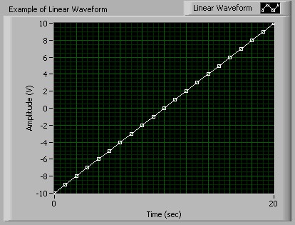
Figure 1. Example of a Linear Waveform
Linear Waveform Applications with CompactRIO
CompactRIO gives engineers and scientists a customizable, rugged, and portable hardware solution for linear waveform generation. The LabVIEW FPGA Module, used with CompactRIO hardware, provides maximum flexibility for the developer. Developers can build hardware modules with CompactRIO that provide custom tasks, timing, and triggering. The ability to output linear waveforms empowers engineers to utilize linear functions in any application that requires a voltage ramp . For instance, an engineer could perform a test over a range of acceptable voltages for a unit under test by generating a voltage ramp. With the flexibility of CompactRIO they could also develop a custom analog input module to analyze the response.
The flexibility of CompactRIO enables developers to customize their generation to continuously change the update rate, gain, and even the waveform during execution. In addition, the LabVIEW FPGA Module delivers the ability to easily customize the timing and triggering of FPGA functions on the same CompactRIO hardware with 25 nanosecond resolution. This functionality is beneficial if an application requires the tight synchronization of a linear response to another factor, such as an external signal. Furthermore, the customization of CompactRIO for specific applications often leads to significant cost benefits for both the developer and the end-user.
Voltage Output with CompactRIO Analog Output Modules
The LabVIEW FPGA Module utilizes integer math for all mathematical operations; therefore, analog output operations with CompactRIO must utilize the binary code representation of the desired output voltage. The binary code representation of a desired voltage is determined by dividing the desired voltage by the code width of the module. The code width (or step size) of a module is defined as the smallest change in voltage that the system can output. Code width is calculated according to the following equation:
For example, the cRIO-9263 analog output module has 16-bit analog output channels with a range of -10V to 10V. Therefore the code width of the module is .305176mV/step (20V / 2^16 steps). Therefore, to output 5.0 volts, you would need to divide 5.0 V by .305176mV. This division yields a binary value of 16384.
NI has included a VI with each analog output module that will do this conversion for you. This VI will be named Convert to Binary (cRIO-XXXX), where XXXX is the model number of the module. It will be included in the cRIO-XXXX Support Files LLB located in the \examples\FPGA\CompactRIO\cRIO-XXXX\ directory. This VI (Figure 2) is often used in FPGA VIs to convert desired voltage values into the binary code representation of that voltage. You will supply it the voltage you want to output in the Nominal Value (V) terminal. The Calibration terminal is a cluster that includes two different controls: Offset (nV) and LSB Weight (nV/LSB). These controls are used to determine the binary code representation of the voltage, which is returned through the Binary Value terminal. The LSB Weight (nV/LSB) is the code width of the module, and the Offset (nV) corresponds to any offset you may want to recognize.
Figure 2. Convert to Binary (cRIO-9263) VI
Linear Waveform Generation with Array Operations
There are many ways to perform linear waveform generation in CompactRIO. The different methods range from array operations to the more advanced memory read and write operations. This range of different methods gives developers many different options that can be utilized in various applications. One quick, easy way to generate any waveform is by including points in an array and indexing through those points at specific time intervals.
Arrays in the LabVIEW FPGA Module
Arrays can be created with the LabVIEW FPGA Module; however, you can only use fixed-size, one dimensional arrays. You can make any array constant, control, or indicator fixed-size, by right clicking on the array index and selecting Set Dimension Size. If your values will always remain the same, use arrays of constants because they are more efficient in FPGA VIs. Note: To optimize compile time, avoid using arrays larger than 32 elements because they require space on the FPGA.
Creating a LabVIEW FPGA VI to Output an Array
The first step in developing any application in the LabVIEW FPGA Module is to develop a VI that will be run (or synthesized) on the FPGA. An FPGA VI that cycles through an array is shown in Figure 3. This VI (Array Output VI) utilizes the Auto-Indexing feature of LabVIEW to index through the array point-by-point. The output values are extracted from the array and then are output on analog output channel 0 of a cRIO-9263 analog output module.
This program uses a Sequence Structure as recommended in the LabVIEW FPGA Module User Manual for timed I/O operations. In the first sequence we are using the Loop Timer function to control the update rate of the analog output. With CompactRIO all of the hardware timing is defined in our software, therefore we can change the update rate during execution by simply changing the value in the Update Period (mSec) control. The loop in this program will execute at a rate defined by 1/Update Period (mSec). The cRIO-9263 has a minimum update period of 3 microseconds when outputting data to one analog output channel. This corresponds to a maximum update rate of 333,333 updates/sec. In the second sequence of the program we are using the Analog Output function to output the desired voltage to channel 0 on a cRIO-9263.
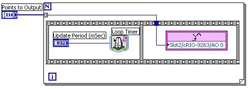
Figure 3. Array Output VI
Creating a Host VI to Execute the Targeted VI
The second step of most LabVIEW FPGA applications is to create a host interface VI to communicate with the FPGA VI downloaded to the hardware target. The Execute Array Output VI, shown in Figure 4, opens a reference to Array Output VI that has been downloaded to the FPGA controller with the Open FPGA Reference function. It then sets the values for the Points to Output and Update Period (mSec) controls of the VI with the Read/Write Control function. The VI is then actually run on the FPGA by using the Invoke Method function with the Run command. It waits until the VI is through running, then it closes the reference with the Close FPGA VI Reference function and checks for errors.

Figure 4. Execute Array Output VI
Indexing through arrays for waveform generation is perfectly acceptable for waveforms that are defined by a relatively small number of points. Remember that each element in the array consumes many gates on the FPGA; therefore, large arrays are not practical with the LabVIEW FPGA Module. However, the FPGAs do 16KB of memory that can be utilized for storage. This memory can be accessed using the Memory Read and Memory Write VIs located on the Functions>>FGPA Device I/O>>Advanced FPGA Device I/O pallette.
Linear Interpolation with the LabVIEW FPGA Module
The LabVIEW FPGA Module provides a very powerful method for developers to define a linear waveform without creating an array of values. With the LabVIEW FPGA Module you can use the Linear Interpolation VI to easily calculate values along a linear waveform. The Linear Interpolation VI (Figure 5) has three inputs: y0, y1, and x (fractional). y0 is the lower bound and y1 is the upper bound of the interpolation interval. x (fractional) represents the evaluation point within the interval [y0,y1). x (fractional) is an unsigned 16-bit integer that represents a fractional number in the range [0,1) that corresponds to the interval created by [y0,y1). For example, an x (fractional) value of 0 will give you the value (returned in the y terminal) at y0 and an x (fractional) value of 32767 will give you the value half-way between y0 and y1.

Figure 5. Linear Interpolation VI
With this VI, you only need to provide the start and end points and interpolation evaluation points to define a waveform. For example, if you wanted to output 5 total points, you could output y0, values at 1/4, 1/2, and 3/4 of the way between y0 and y1 and then y1. This waveform can be created by performing linear interpolation with x (fractional) values of 0, 16383, 32767, 49151, and then outputting the value at y1. The value at y1 is explicitly output because the linear interpolation evaluates on the interval of [y0,y1) which does not include y1 at the end. Therefore, an x (fractional) value of 65535 will not necessarily output the value at y1.
Linear Waveform Generation with Linear Interpolation
You can use the Linear Interpolation VI with LabVIEW FPGA to generate a linear waveform by supplying y0 (start point) and y1 (end point), the number of points to interpolate, and the x (fractional) values. The interpolation locations can be determined programmatically, often with a running summation. The Output Linear Waveform VI, shown in Figure 6, utilizes this method. This VI will output the number of points defined in the Number of Points control with the interpolation based on the Start Point and End Point controls. The linear interpolation will initially be done at an x (fractional) value of 0, and that value will increase each iteration by the Interpolation Increment value.
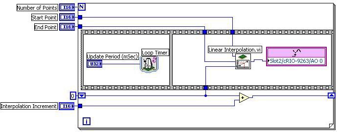
Figure 6. Output Linear Waveform VI
You can execute this VI by manually supplying the control values and running the VI. You can also develop a VI that will be run on the host that programmatically executes and communicates with this VI. The Execute - Output Linear Waveform VI, shown in Figure 7, is developed and run on the host machine. It uses the Open FPGA Reference, Read/Write Control, Invoke Method, and Close FPGA Reference functions. These functions provide all of the necessary control over the FPGA, such as downloading, reading or writing data, and starting or stopping the VI. This method allows you to quickly change the values of the controls required for execution. You could even take this VI and use it in other VIs to perform output on the cRIO-9263 as part of a larger project.

Figure 7. Execute - Output Linear Waveform VI
An Example Interpolation Algorithm
The previous example highlights a generic method to generate a linear waveform based on linear interpolation. You can write your own algorithm to determine the values that you will output along the line defined by the start and end points. A common algorithm to use is one that allows you to add evenly spaced points between the start and end points to output a waveform with more resolution. Determining the evaluation points at can be done with a host VI that will determines the spacing between 0 and 65535 necessary to fit points between the start and end point. You could also have an algorithm in the FPGA VI that determines the evaluation points programmatically. This method enables you to simply tell the FPGA code how many points to place between the start and end point and therefore the sampling rate for the waveform.
One such algorithm can be easily implemented by taking advantage of the binary representations of integers and the Linear Interpolation VI. If you look back to the Linear Interpolation with the LabVIEW FPGA Module section, we discussed the x (fractional) control. It is a 16-bit integer that represents the location between the two points where the interpolation will occur. Recall that a value of 0 represents the starting point (y0) and a value of 32767 represented half way between y0 and y1. The full range of x (fractional) is 65535. Half of this value is 32767, one quarter is 16383, and one-eighth is 8191. If we look at the binary representations of these numbers (Figure 8), we see that the binary representation of these numbers is just the previous shifted one place to the right (divided in half in binary).

Figure 8. Integer and Binary Representations of Interpolation Locations
We can take advantage of this binary shifting to quickly determine what the values of x (fractional) should be to add 1, 3, 7, (2^n -1) etc. points between y0 and y1. Notice that if we are to add 1 point, it would be at x (fractional) value of 32767 (65535 shifted right once). If we were to add 3 points, the x (fractional) values would be at 16383, 32767, and 49151 to represent 1/4, 1/2 and 3/4 of the way between y0 and y1. If you look closely at the binary representation of these numbers you will notice that 32767 is 16383 + 16383 with a 1 ORed in the least significant place, and 49151 is 32767 + 16383 with a 1 ORed in the least significant place. This same pattern surfaces for any 2^n - 1 points that are to be added between the start and end point. Therefore, if you wanted to add 2^n-1 points between the start and end point you could shift 65535 right by n places to get the first interpolation point. You then determine the rest of the points by adding this initial value and doing an OR with a value of 1. When you get to 65535, the largest value that can be interpolated at, the interpolation value is replaced with the value at the End Point. The reason for this replacement is because the interpolation interval, [y0,y1), does not include the end value, so we configure the output to be the end point for the final update.
The Linear Output - Adding Points VI, shown in Figure 9, uses this algorithm to output the start point, the 2^n -1 (for n = 0:15) points in between, and the end point. The Points to Add (2^n-1) control determines the number of points included between the start and end point. Notice that it is negated and then the value 65535 is shifted by this amount, which amounts to a right-shift by n places. The Sequence structure inside the while loop includes two sequences. The first sequence (not shown) has a Loop Timer VI and a Period Update (mSec). This sequence is used to create a timed update rate of the points, similar to the other two examples in this tutorial. The second sequence is where the actual output is done. Each iteration, the interpolation is done at the location passed into the x (fractional) terminal of the Linear Interpolation VI. This value is output on channel 0 of the cRIO-9263 module. The next interpolation value is calculated by adding the result of the initial shifting of 65535 and then that result is ORed with 1 and wired to the shift register for the next iteration. In the final iteration (when the interpolation point is 65535), the value in the End Point control is output and the program ends.
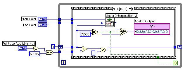
Figure 9. Linear Output - Adding Points VI
Once again, you can develop a VI that can be run on a host that will programmatically execute this VI. The following VI, Execute Linear Output - Adding Points, is developed and run on the host machine. With this VI on the host, you can call the VI multiple times without having to manually interface with the VI on the FPGA, and you can use this VI as a SubVI in other VIs.

Figure 10. Execute Linear Output - Adding Points VI
Piecewise-linear Waveform Generation with Linear Interpolation
A piecewise-linear waveform is a waveform that is constructed by a combination of linear waveforms. The entire waveform is not linear, but individual sections include linear waveforms. You can use the methods described in the previous sections to output a piecewise linear function. You could easily create an array that describes the waveform by individual points and you could output that waveform with the Array Output VI described in the Linear Waveform Generation with Array Operations section. However, remember that arrays consume gates on the FPGA and you should not create an array of larger than 32 elements. Therefore, you could use the array method to output the waveform, but remember that your number of output points is limited.
You can use a combination of the VIs used in the Linear Waveform Generation with Array Operations and Linear Waveform Generation with Linear Interpolation sections to create a waveform generator capable of outputting thousands of points. We have already described how you can define a linear waveform by a start and end point and can determine points between these two points with linear interpolation. You can expand this method to piecewise-linear waveforms by recognizing that you can define a piecewise linear waveform by the start and end points of each linear segment. You can then determine points in each segment by interpolating between the start and end points of the linear segments.
The location of the interpolation can be determined in many different ways. We described one method of determining the interpolation locations that takes advantage of the binary representation of the x (fractional) value. We can utilize this algorithm to output a repeating piecewise linear waveform by applying it for each linear segment. An example of this application can be seen in the Piece-wise Linear Output - Added Points VI, shown in Figure 11, which outputs a continuous waveform.
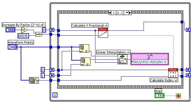
Figure 11. Piece-wise Linear Output - Added Points VI.
This VI includes two subVIs, Calculate X Fractional, shown in Figure 12, and Calculate Index, shown in Figure 13, that enable it to cycle through each linear segment and output points between the start and end point of each linear segment. The Calculate X Fractional VI accepts the interpolation location (Current X Fractional) and the distance between interpolation locations (Point By Point Increment). The Calculate X Fractional VI adds the Point By Point Increment, which is determined by shifting 65535 over by n places. This addition is then ORed with 1, just as in the previous algorithm. When we were outputting the single linear waveform we output the end point (y1) when we reached an x (Fractional) value of 65535. However, we are now outputting a continuous piecewise-linear waveform so we can output the start point of the next segment if we assume no discontinuities in the waveform. This value should actually be the same array location as the previous y1. Therefore, when we reach an interpolation location of 65535, we simply reset the interpolation location to 0 and increment the start and end points by one. The Calculate X Fractional VI accounts for this rollover by checking to see if the result of adding the increment equals 65535. If it does, then it resets the next interpolation location (Next X Fractional) to 0 and returns a TRUE value through the Rollover ? terminal, which is wired to the Calculate Index VI.


Figure 12. Calculate X Fractional VI
The Calculate Index VI uses the results of the Calculate X Fractional VI to determine the next start and end points (Low Index (Out) and High Index Out) of the interpolation. If rollover has occurred (meaning all of the points in the last segment have been output), then the Low Index and High Index are incremented. However, since we are outputting a repeating waveform, we must roll the index back around to the beginning of the array. This rollover is done by resetting the Low Index and High Index to 0 when each passes the last element in the array. This change is done by comparing the values to the size of the array.


Figure 13. Calculate Index VI
You can easily modify this example to output the waveform just one time by recognizing when the High Index is at the last point in the Waveform Points array. You can then set the terminal condition on the while loop to TRUE after the last point in that segment is output. Remember that you can also use the memory on the FPGA to store points in the piecewise-linear waveform. This example could easily be modified to read the start and end points from the memory if you have many linear segments in the waveform.
Conclusion
CompactRIO gives engineers and scientists a customizable, rugged, and portable solution for linear waveform generation. The LabVIEW FPGA Module, used to program the CompactRIO hardware, provides maximum flexibility for the developer. It gives developers the freedom to create unique modules with hardware-timed functionality. By taking advantage of the array operations and linear interpolation features in the LabVIEW FPGA Module a developer can easily create a waveform generator that will output linear waveforms. There is more functionality in the LabVIEW FPGA Module that allows you to perform output of non-linear, periodic, and arbitrary waveforms.