Getting Started with DAQmx: DAQmx Events
Contents
Overview
NI-DAQmx Events in LabVIEW provide a way of generating a signal from the hardware or a software interrupt when certain conditions are met on the data acquisition hardware. The main advantage of using NI-DAQmx events is that it is not processor intensive and does not block access to any other driver call to a DAQ device since NI-DAQmx is multithreaded.
NI-DAQmx Events can be used for PC buffer monitoring and can be used in conjunction with DMA data transfer. However, they are not used for transferring data across the PCI bus.
NI-DAQmx Events can be generated both at hardware and software level.
NI-DAQmx Hardware Events
Generally, triggers and clocks are input signals but exportable triggers and clocks, such as the sample clock, also can be output signals. Output signals that do not have a trigger or clock counterpart are called hardware events. Events are generated to signify a device state change, the arrival of a certain kind of sample, the production of a certain amount of samples, or the passage of time.
NI-DAQmx includes the following hardware events:
- Advance Complete Event—A signal emitted by a switch when it has finished executing an instruction in its scan list.
- AI Hold Complete Event—A signal emitted by a multiplexed analog input circuit when the analog signal at the physical channel being measured has been latched or held. The AI Hold Complete Event is designed to signal an external multiplexer to switch to the next channel. This signal was previously known as SCANCLK, which is the legacy name of the external terminal where this signal can be emitted.
- Change Detection Event—A signal a DIO device generates after it detects a change on the data lines.
- Counter Output Event—A signal produced by a counter when it reaches terminal count.
- Handshake Event—A signal generated by a DAQ device that is used for handshaking. The assertion and deassertion times for this event are configurable within a handshaking cycle for some devices. For these devices, the default configuration is to mimic the 8255 protocol, which means that for input tasks, this event asserts after the device has space available in its FIFO; for output tasks, it asserts after valid data has been driven on the data lines; and in both input and output tasks, the event deasserts after the Handshake Trigger has been asserted.
- Ready For Transfer Event—A signal sent to the peripheral device that signals that the DAQ device is ready for a transfer. For burst handshake output tasks, this means that the data is on the data lines. For input tasks, this means that there is space available in the device FIFO. This event is used by devices that support burst handshake timing.
- Sample Complete Event—A signal produced when the device acquires a sample from every channel in a task.
- Watchdog Timer Expired Event—A signal produced when a watchdog timer expires.
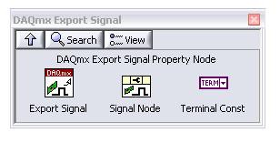
To set these events in LabVIEW use the DAQmx Export Signal Property Node. This is located in LabVIEW under Measurement I/O >>DAQmx-Data acquisition >> DAQmx Advanced Task Options >> DAQmx Export Signal as shown in Figure 1.
Figure 1. DAQmx Export Signal Property Node
With the DAQmx Export Signal Property Node, you can select the Event polymorphic instance such as AI Hold Complete Events, Change Detection Events, Counter Output Events as shown in Figure 2.
Figure 2 Counter output event properties
Others are located in in LabVIEW under Measurement I/O >>DAQmx-Data acquisition >> DAQmx Advanced Task Options sub-palette and in LabVIEW under Measurement I/O >>DAQmx-Data acquisition >> DAQmx Device Configuration >> watchdog sub-palette.
DAQmx Software Events
Software events provide an asynchronous notification mechanism for a set of DAQ events. Unlike hardware events, software events do not require you to use a thread to wait until data is available. Using event-based programming, you can write an application that continues to perform work while waiting for data without resorting to developing a multi-threaded application.
NI-DAQmx includes the following software events:
- Every N Samples Acquired Into Buffer Event—Occurs when the user-defined number of samples is written from the device to the PC buffer. This event works only with devices that support buffered tasks.
- Every N Samples Transferred From Buffer Event—Occurs when the user-defined number of samples is written from the PC buffer to the device. This event works only with devices that support buffered tasks.
- Done Event—Occurs when the task completes execution or when an error causes the task to finish. Recoverable errors that do not cause the task to finish do not cause this event to fire. Calling the Stop function/VI to complete execution similarly does not cause this event to fire. Use the DAQmx Task Done property node located in LabVIEW under Measurement I/O >>DAQmx-Data acquisition >> DAQmx Advanced Task Options.
- Signal Event—Occurs when the specified hardware signal occurs. Supported signals include the counter output event, change detection event, sample complete event, and the sample clock.
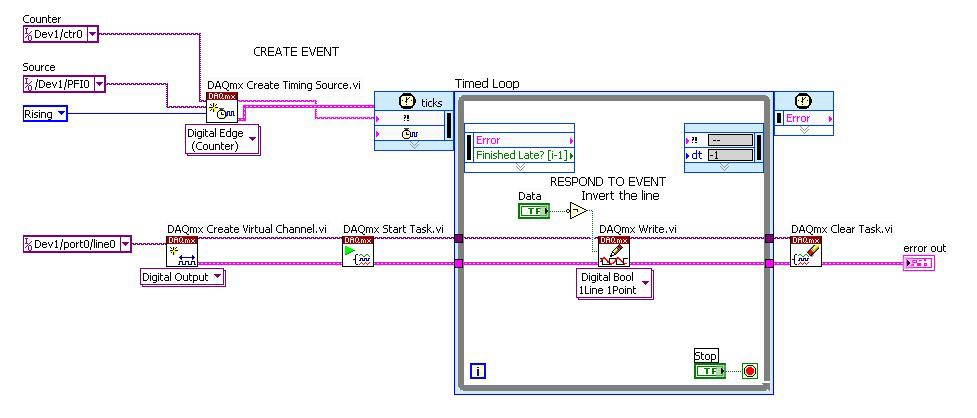
Figure 3 is a block diagram for an event-response application. Programmatically, the event, in this instance, is a rising edge on a digital line, PFI0. The response is the execution of the Timed Loop structure, which sets a digital line, line0. To create a real-time event response application with the Timed Loop and a DAQ device, you need to use the Create Timing Source VI.
Figure 3. Creating Events with Timing Source VI.


