NI LabVIEW Compiler: Under the Hood
Overview
Contents
- Compilation versus Interpretation
- A Historical Perspective of the LabVIEW Compiler
- Today’s Compile Process
- The DFIR and LLVM Work in Tandem
This particular paper introduces the LabVIEW compiler, briefly explains its evolution starting in 1986 with LabVIEW 1.0, and describes its form today. Additionally, it explores recent compiler innovations and highlights the advantages of these new features to the LabVIEW architecture and to you.
Compilation versus Interpretation
LabVIEW is a compiled language, which can be surprising because during typical G development, there is no explicit compile step. Instead, you make a change to your VI and simply press the Run button to execute it. Compilation means that the G code you write is translated into native machine code and is then executed directly by the host computer. An alternative to this approach is interpretation, where programs are indirectly executed by another software program (called the interpreter) instead of directly by the computer.
Nothing about the LabVIEW language requires it to be either compiled or interpreted; in fact, the first version of LabVIEW used an interpreter. In later versions, the compiler replaced the interpreter to boost VI run-time performance, which is a common differentiator for compilers relative to interpreters. Interpreters tend to be easier to write and maintain at the cost of slower run-time performance, while compilers tend to be more complex to implement but offer faster execution times. One of the primary benefits of the LabVIEW compiler is that improvements made to the compiler are seen by all VIs without the need for any changes. In fact, one of the primary focuses for the 2010 release of LabVIEW was optimizations inside the compiler to speed VI execution time.
A Historical Perspective of the LabVIEW Compiler
Before jumping into an in-depth discussion of the present-day compiler’s internals, it is worthwhile to summarize the development of the compiler from its earliest forms more than 20 years ago. Some of the algorithms introduced here, such as type propagation, clumping, and inplaceness, are described in more detail in the modern LabVIEW compiler discussion.
LabVIEW 1.0 shipped in 1986. As previously mentioned LabVIEW used an interpreter in its first version and targeted only the Motorola 68000. The LabVIEW language was much simpler in those days, which also lessened the requirements on the compiler (then an interpreter). For example, there was no polymorphism and the only numeric type was extended precision floating-point. LabVIEW 1.1 saw the introduction of the inplaceness algorithm, or the “inplacer.” This algorithm indentifies data allocations that you can reuse during execution, which prevents unnecessary data copies and, in turn, speeds up execution performance often dramatically.
In LabVIEW 2.0, the interpreter was replaced with an actual compiler. Still targeting the Motorola 68000 exclusively, LabVIEW could generate native machine code. Also added in Version 2.0 was the type propagation algorithm, which, among other duties, handles syntax checking and type resolution on the growing LabVIEW language. Another large innovation in LabVIEW 2.0 was the introduction of the clumper. The clumping algorithm identifies parallelism in the LabVIEW diagram and groups nodes into “clumps,” which can run in parallel. The type propagation, inplaceness, and clumping algorithms continue to be important components of the modern LabVIEW compiler and have seen numerous incremental improvements over time. The new compiler infrastructure in LabVIEW 2.5 added support for multiple back ends, specifically Intel x86 and Sparc. LabVIEW 2.5 also introduced the linker, which manages dependencies between VIs to track when they need to be recompiled.
Two new back ends, PowerPC and HP PA-RISC, were added along with constant folding in LabVIEW 3.1. LabVIEW 5.0 and 6.0 revamped the code generator and added the GenAPI, a common interface to the multiple back ends. The GenAPI cross compiles, which is important for real-time development. Real-time developers typically write VIs on a host PC but deploy them to (and compile them for) a real-time target. Additionally, a limited form of loop-invariant code motion was included. Finally, the LabVIEW multitasking execution system was extended to support multiple threads.
LabVIEW 8.0 built on the GenAPI infrastructure introduced in Version 5.0 to add a register allocation algorithm. Prior to the introduction of the GenAPI, registers were hardcoded in the generated code for each node. Limited forms of unreachable code and dead code elimination were also introduced. LabVIEW 2009 featured 64-bit LabVIEW and Dataflow Intermediate Representation (DFIR). The DFIR was immediately used to build more advanced forms of loop-invariant code motion, constant folding, dead code elimination, and unreachable code elimination. New language features introduced in 2009, like the parallel For Loop, were built on the DFIR.
Finally, in LabVIEW 2010, the DFIR offers new compiler optimizations such as algebraic reassociation, common subexpression elimination, loop unrolling, and subVI inlining. This release also includes the adoption of a Low-Level Virtual Machine (LLVM) into the LabVIEW compiler chain. LLVM is an open-source compiler infrastructure used widely in industry. With LLVM, new optimizations were added such as instruction scheduling, loop unswitching, instruction combining, conditional propagation, and a more sophisticated register allocator.
Today’s Compile Process
With a basic understanding of the LabVIEW compiler history, you can now explore the compile process in modern LabVIEW. First, review a high-level overview of the various compile steps and then revisit each part in more detail.
The first step in the compilation of a VI is the type propagation algorithm. This complex step is responsible for resolving implied types for terminals that can adapt to type, as well as detecting syntax errors. All possible syntax errors in the G programming language are detected during the type propagation algorithm. If the algorithm determines that the VI is valid, then the compilation continues.
After type propagation, the VI is first converted from the model used by the block diagram editor into the DFIR used by the compiler. Once converted to the DFIR, the compiler executes several transforms on the DFIR graph to decompose it, optimize it, and prepare it for code generation. Many of the compiler optimizations – for example, the inplacer and clumper – are implemented as transforms and run in this step.
After the DFIR graph has been optimized and simplified, it is translated into the LLVM intermediate representation. A series of LLVM passes is run over the intermediate representation to further optimize and lower it, eventually to machine code.
Type Propagation
As previously mentioned the type propagation algorithm resolves types and detects programming errors. In fact, this algorithm has several responsibilities including the following:
- Resolving implied types for terminals that can adapt to type
- Resolving subVI calls and determining their validity
- Calculating wire direction
- Checking for cycles in the VI
- Detecting and reporting syntax errors
This algorithm runs after each change you make to a VI to determine if the VI is still good, so whether this step is really part of “compile” is a little debatable. However, it is the step in the LabVIEW compile chain that most clearly corresponds to the lexical analysis, parsing, or semantic analysis steps in a traditional compiler.
A simple example of a terminal that adapts to type is the add primitive in LabVIEW. If you add two integers, the result is an integer, but if you add two floating-point numbers, the result is a floating-point number. Similar patterns exist for compound types such as arrays and clusters. There are other language constructs like shift registers that have more complex typing rules. In the case of the add primitive, the output type is determined from the input types, and the type is said to “propagate” through the diagram, hence the name of the algorithm.
This add primitive example also illustrates the syntax-checking responsibility of the type propagation algorithm. Suppose you wire an integer and a string to an add primitive – what should happen? In this case, adding these two values doesn't make sense, so the type propagation algorithm reports this as an error and marks the VI as “bad,” which causes the run arrow to break.
Intermediate Representations – What and Why
After type propagation decides that a VI is valid, compile continues and the VI is translated to the DFIR. Consider intermediate representations (IRs) in general before detailing the DFIR.
An IR is a representation of the user’s program that is manipulated as the compile progresses through various phases. The notion of an IR is common among modern compiler literature and can be applied to any programming language.
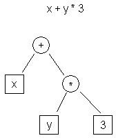
Consider some examples. There are a variety of popular IRs today. Two common examples are abstract syntax trees (AST) and three-address code.
 | t0 <- y t1 <- 3 t2 <- t0 * t1 t3 <- x t4 <- t3 + t2 |
| Figure 1. AST IR Example | Table 1. Three-Address Code IR Example |
Figure 1 shows the AST representation of the expression “x + y * 3,” while Table 1 shows the three-address code representation.
One obvious difference between these two representations is that the AST is much higher-level. It is closer to the source representation of the program (C) than the target representation (machine code). The three-address code, by contrast, is low-level and looks similar to assembly.
Both high- and low-level representations have their advantages. For example, analyses such as dependence analysis might be easier to perform on a high-level representation like the AST than on a low-level one like three-address code. Other optimizations, such as register allocation or instruction scheduling, are typically performed on a low-level representation like three-address code.
Because different IRs have different strengths and weaknesses, many compilers (including LabVIEW) use multiple IRs. In the case of LabVIEW, the DFIR is used as a high-level IR, while the LLVM IR is used as a low-level IR.
DFIR
In LabVIEW, the high-level representation is the DFIR, which is hierarchical and graph-based and resembles G code itself. Like G, the DFIR is composed of various nodes, each of which contains terminals. Terminals can be connected to other terminals. Some nodes like loops contain diagrams, which may in turn contain other nodes.
Figure 2. LabVIEW G Code and an Equivalent DFIR Graph
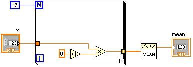
Figure 2 shows a simple VI alongside its initial DFIR representation. When the DFIR graph for a VI is first created, it is a direct translation of the G code, and nodes in the DFIR graph generally have a one-to-one correspondence to nodes in the G code. As the compile progresses, DFIR nodes may be moved or split apart, or new DFIR nodes may be injected. One of the key advantages of the DFIR is that it preserves characteristics like the parallelism inherent in your G code. Parallelism represented in three-address code, by contrast, is much harder to discern.
The DFIR offers two significant advantages to the LabVIEW compiler. First, the DFIR decouples the editor from the compiler representation of the VI. Second, the DFIR serves as a common hub for the compiler, which has multiple front and back ends. Consider each of these advantages in more detail.
The DFIR Graph Decouples the Editor from the Compiler Representation
Before the advent of DFIR, LabVIEW had a single representation of the VI that was shared by both the editor and the compiler. This prohibited the compiler from modifying the representation during the compile process, which, in turn, made it difficult to introduce compiler optimizations.
Figure 3. DFIR Provides a Framework that Allows the Compile to Optimize Your Code
Figure 3 shows a DFIR graph for the VI introduced earlier. This graph depicts a time much later in the compiler process after several transforms have decomposed and optimized it. As you can see, this graph looks quite a bit different from the previous graph. For example:
- Decomposition transforms have removed the Control, Indicator, and SubVI nodes and replaced them with new nodes – UIAccessor, UIUpdater, FunctionResolver, and FunctionCall
- Loop-invariant code motion has moved the increment and multiply nodes outside the loop body
- The clumper has injected a YieldIfNeeded node inside the For Loop, which causes the executing thread to share execution with other competing work items
Transforms are covered in more detail in a later section.
The DFIR IR Serves as a Common Hub for the Multiple Compiler Front and Back Ends
LabVIEW works with several different targets, some of which are dramatically different from one another, for example, an x86 desktop PC and a Xilinx FPGA. Similarly, LabVIEW presents multiple models of computation to the user. In addition to graphical programming in G, LabVIEW offers text-based mathematics in MathScript, for example. This results in a collection of front and back ends, all of which need to work with the LabVIEW compiler. Using the DFIR as a common IR that all the front ends produce and all the back ends consume facilitates reuse between the various combinations. For example, an implementation of a constant folding optimization that runs on a DFIR graph can be written once and applied to desktop, real-time, FPGA, and embedded targets.
DFIR Decompositions
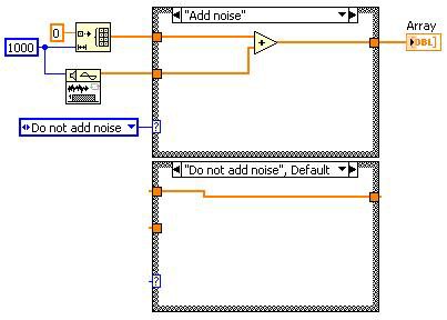
Once in DFIR, the VI first runs through a series of decomposition transforms. Decomposition transforms aim to reduce or normalize the DFIR graph. For example, the unwired output tunnel decomposition finds output tunnels on case structures and event structures that are unwired and configured to “Use Default If Unwired.” For those terminals, the transform drops a constant with the default value and wires it to the terminal, thus making the “Use Default If Unwired” behavior explicit in the DFIR graph. Subsequent compiler passes can then treat all terminals identically and assume they all have wired inputs. In this case, the “Use Default If Unwired” feature of the language has been “compiled away” by reducing the representation to a more fundamental form.
This idea can be applied to more complex language features as well. For example, a decomposition transform is used to reduce the Feedback Node into shift registers on a While Loop. Another decomposition implements the parallel For Loop as several sequential For Loops with some additional logic to split inputs into parallelizable pieces for the sequential loops and join the pieces back together afterward.
A new feature in LabVIEW 2010, subVI inlining, is also implemented as a DFIR decomposition. During this phase of compile, the DFIR graph of subVIs marked “inline” is injected directly into the caller’s DFIR graph. In addition to avoiding the overhead of a subVI call, inlining exposes additional optimization opportunities by combining the caller and callee into a single DFIR graph. For example, consider this simple VI that calls the TrimWhitespace.vi from vi.lib.
Figure 4. Simple VI Example to Demonstrate DFIR Optimizations
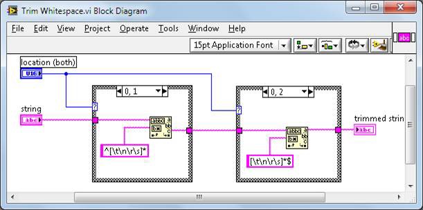
The TrimWhitespace.vi is defined in vi.lib like this:
Figure 5. TrimWhitespace.vi Block Diagram
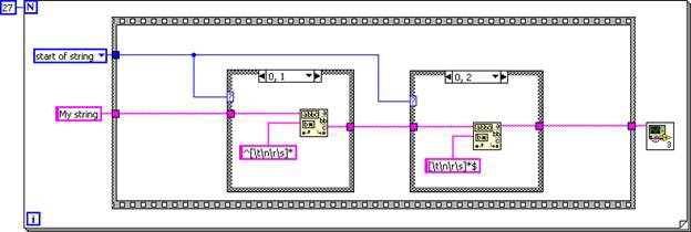
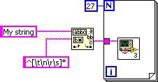
The subVI is inlined into the caller, resulting in a DFIR graph equivalent to the following G code.
Figure 6. G Code Equivalent of the Inlined TrimWhitespace.vi DFIR Graph
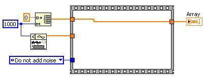
Now that the subVI’s diagram is inlined into the caller diagram, unreachable code elimination and dead code elimination can simplify the code. The first case structure always executes, while the second case structure never executes.
Figure 7. The Case Structures Can Be Removed Because the Input Logic is Constant
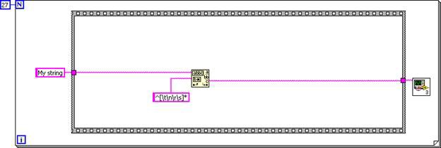
Similarly, loop-invariant code motion moves the match pattern primitive out of the loop. The final DFIR graph is equivalent to the following G code.
Figure 8. G Code Equivalent for the Final DFIR Graph
Because TrimWhitespace.vi is marked as inline in LabVIEW 2010 by default, all clients of this VI receive these benefits automatically.
DFIR Optimizations
After the DFIR graph is thoroughly decomposed, the DFIR optimization passes begin. Even more optimizations are performed later during the LLVM compile. This section covers only a handful of the many optimizations. Each of these transforms is a common compiler optimization, so it should be easy to find more information on a specific optimization.
Unreachable Code Elimination
Code that can never execute is unreachable. Removing unreachable code does not directly make your execution time much faster, but it does make your code smaller and boosts compile times because the removed code is never traversed again in subsequent compile passes.
Before Unreachable Code Elimination
After Unreachable Code Elimination
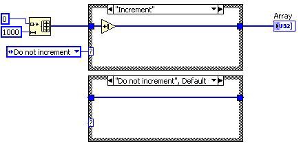
Figure 9. G Code Equivalent for the DFIR Unreachable Code Elimination Decomposition
In this case, the “Increment” diagram of the case structure is never executed, so the transform removes that case. Because the case structure has only one remaining case, it is replaced with a sequence structure. Dead code elimination later removes the frame and enumerated constant.
Loop-Invariant Code Motion
Loop-invariant code motion identifies code inside the body of a loop that you can safely move outside. Because the moved code is executed fewer times, overall execution speed improves.
Before Loop Invariant Code Motion Transform | After Loop Invariant Code Motion Transform |
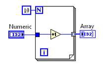
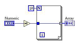
Figure 10. G Code Equivalent for the DFIR Loop-Invariant Code Motion Decomposition
In this case, the increment operation is moved outside the loop. The loop body remains so the array can be built, but calculation does not need to be repeated in each iteration.
Common Subexpression Elimination
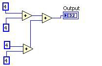
Common subexpression elimination identifies repeated calculations, performs the calculation only once, and reuses the results.
Before After
Figure 11. G Code Equivalent for the DFIR Common Subexpression Elimination Decomposition
Constant Folding
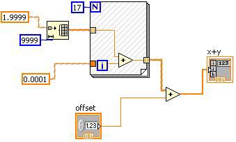
Constant folding identifies parts of a diagram that are constant at run time and therefore can be determined early.
Figure 12. Constant Folding Can Be Visualized in the LabVIEW Block Diagram
The hash marks on the VI in Figure 12 indicate the constant-folded portion. In this case, the “offset” control cannot be constant folded, but the other operand of the plus primitive, including the For Loop, is constant-valued.
Loop Unrolling
Loop unrolling reduces loop overhead by repeating a loop’s body multiple times in the generated code and reducing the total iteration count by the same factor. This reduces loop overhead and exposes opportunities for further optimizations at the expense of some increase in code size.
Dead Code Elimination
Dead code is code that is unnecessary. Removing dead code speeds up execution time because the removed code is no longer executed.
Dead code is usually produced by the manipulation of the DFIR graph by transforms you did not write directly. Consider the following example. Unreachable code elimination determines that the case structure can be removed. This “creates” dead code for the dead code elimination transform to remove.
Before
After Unreachable Code Elimination
After Dead Code Elimination
Figure 13. Dead Code Elimination Can Reduce the Amount of Code the Compiler Has to Traverse
Most of the transforms covered in this section feature interrelationships like this; running one transform may uncover opportunities for other transforms to run.
DFIR Back-End Transforms
After the DFIR graph is decomposed and optimized, a number of back-end transforms execute. These transforms evaluate and annotate the DFIR graph in preparation for ultimately lowering the DFIR graph to the LLVM IR.
Clumper
The clumping algorithm analyzes parallelism in the DFIR graph and groups nodes into clumps that you can run in parallel. This algorithm is closely tied to the run-time execution system of LabVIEW, which uses multithreaded cooperative multitasking. Each of the clumps produced by the clumper is scheduled as an individual task in the execution system. Nodes within clumps execute in a fixed, serialized order. Having a predetermined execution order with each clump allows the inplacer to share data allocations and dramatically improves performance. The clumper is also responsible for inserting yields into lengthy operations, like loops or I/O, so that those clumps cooperatively multitask with other clumps.
Inplacer
The inplacer analyzes the DFIR graph and identifies when you can reuse data allocations and when you must make a copy. A wire in LabVIEW may be a simple 32-bit scalar or a 32 MB array. Making sure that data is reused as much as possible is critical in a dataflow language such as LabVIEW.
Consider the following example (note that the VI’s debugging is disabled to achieve the best performance and memory footprint).
Figure 14. Simple Example Demonstrating the Inplaceness Algorithm
This VI initializes an array, adds some scalar value to each element, and writes it to a binary file. How many copies of the array should there be? LabVIEW has to create the array initially, but the add operation can operate just on that array, in place. Thus only one copy of the array is needed instead of one allocation per wire. This amounts to a significant difference – both in memory consumption and execution time – if the array is large. In this VI, the inplacer recognizes this opportunity to operate “in place” and configure the add node to take advantage of this.
You can inspect this behavior in VIs you write by using the “Show Buffer Allocations” tool under Tools»Profile. The tool does not show an allocation on the add primitive, indicating that no data copy is made and that the add operation happens in place.
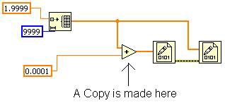
This is possible because no other nodes need the original array. If you modify the VI as shown in Figure 15, then the inplacer has to make a copy for the add primitive. This is because the second Write to Binary File primitive needs the original array and must execute after the first Write to Binary File Primitive. With this modification, the Show Buffer Allocations tool shows an allocation on the add primitive.
Figure 15. Branching the Original Array Wire Causes a Copy to Made in Memory
Allocator
After the inplacer identifies which nodes can share memory locations with other nodes, the allocator runs to create the allocations that the VI needs to execute. This is implemented by visiting each node and terminal. Terminals that are in-place to other terminals reuse allocations rather than creating new ones.
Code Generator
The code generator is the component of the compiler that converts the DFIR graph into executable machine instructions for the target processor. LabVIEW traverses each node in the DFIR graph in dataflow order, and each node calls into an interface known as the GenAPI , which is used to convert the DFIR graph into a sequential intermediate language (IL) form describing the functionality of that node. The IL provides a platform-independent way to describe the low-level behavior of the node. Various instructions in the IL are used to implement arithmetic, read and write to memory, perform comparisons and conditional branches, and so on. IL instructions can operate either on memory or on values held in virtual registers that are used to store intermediate values. Example IL instructions include GenAdd, GenMul, GenIf, GenLabel, and GenMove.
In LabVIEW 2009 and earlier, this IL form was converted directly to machine instructions (such as 80X86 and PowerPC) for the target platform. LabVIEW used a simple one-pass register allocator to map virtual registers to physical machine registers, and each IL instruction emitted a hard-coded set of particular machine instructions to implement it on each supported target platform. While this was blindingly fast, it was ad hoc, produced poor code, and was not well-suited to optimization. The DFIR, being a high-level, platform-independent representation, is limited in the sort of code transformations it can support. To add support for the complete set of code optimizations in a modern optimizing compiler, LabVIEW recently adopted a third-party open source technology called the LLVM.
LLVM
The Low-Level Virtual Machine (LLVM) is a versatile, high-performance open source compiler framework originally invented as a research project at the University of Illinois. The LLVM is now widely used both in academia and industry due to its flexible, clean API and nonrestrictive licensing.
In LabVIEW 2010, the LabVIEW code generator is refactored to use the LLVM to generate target machine code. The existing LabVIEW IL representation provided a good starting point in this endeavor, requiring only approximately 80 IL instructions to be rewritten rather than the much larger set of DFIR nodes and primitives supported by LabVIEW.
After creating the IL code stream from the DFIR graph of a VI, LabVIEW visits each IL instruction and creates an equivalent LLVM assembly representation. It invokes various optimization passes, and then uses the LLVM Just-in-Time (JIT) framework to create executable machine instructions in memory. The LLVM’s machine relocation information is converted into a LabVIEW representation, so when you save the VI to disk and reload it into a different memory base address, you can patch it up correctly to run at the new location.
Some of the standard compiler optimizations LabVIEW uses the LLVM to perform include the following:
- Instruction combining
- Jump threading
- Scalar replacement of aggregates
- Conditional propagation
- Tail call elimination
- Expression reassociation
- Loop invariant code motion
- Loop unswitching and index splitting
- Induction variable simplification
- Loop unrolling
- Global value numbering
- Dead store elimination
- Aggressive dead code elimination
- Sparse conditional constant propagation
A full explanation of all these optimizations is beyond the scope of this paper, but there is a wealth of information about them on the Internet as well as most compiler textbooks.
Internal benchmarks have shown that the introduction of the LLVM has produced an average 20 percent decrease in VI execution time. Individual results depend on the nature of the computations performed by the VI; some VIs see a greater improvement than this and some see no change in performance. For example, VIs that use the advanced analysis library, or are otherwise highly dependent on code that is already implemented in optimized C, see little difference in performance. LabVIEW 2010 is the first version to use the LLVM, and there is still a lot of untapped potential for future improvements.
The DFIR and LLVM Work in Tandem
You may have noticed that some of these optimizations, such as loop-invariant code motion and dead code elimination, were already described as being performed by the DFIR. In fact, some optimization passes are beneficial to run multiple times and at different levels of the compiler because other optimization passes may have transformed the code in such a way that new optimization opportunities are available. The bottom line is that while the DFIR is a high-level IR and the LLVM is a low-level IR, these two work in tandem to optimize the LabVIEW code you write for the processor architecture used for code execution.
