Where to Find NI-DAQmx Device Pinouts or Pin Mappings
Overview
Contents
- NI-DAQmx Pinout and Mapping Locations
- Understanding Device or Module Mapping to Cable and Accessories
- Additional Resources
The device pinouts for a particular NI-DAQmx device should be included in the operating manual for the device. You can also access these pinouts from the NI-DAQmx Device Terminals help file that is installed with DAQmx.
NI-DAQmx Pinout and Mapping Locations
First, it is important to understand that each device or module may use its own pinout or pin mapping scheme. Typically, families of devices with the same pin count will use the same numbering and signal combinations. Always verify you are using the correct pinout for your device. There are several resources you can use to find this scheme.
- Quick Reference Labels - If available, this is the easiest and quickest way to find your signal mapping. The quick reference label is recommended to be printed and attached to your accessory.
- Manuals, User Guides and Specifications - Depending on your model, your device's pinout will be listed inside of its published documentation. You can search NI Manuals for your device.
- NI-DAQmx Help - NI-DAQmx Help installs locally with your driver, and is also available online. The NI-DAQmx Device Terminals Help section contains the pinouts for every hardware model supported by that version of the driver.
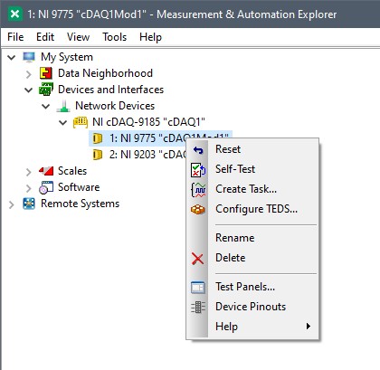
- Measurement & Automation Explorer (MAX) - NI MAX is used to configure your NI DAQ hardware, and also references out to many different types of reference information, including device pinouts. Right-click your device name under Devices and Interfaces, and select Device Pinouts to directly navigate to the NI-DAQmx Device Terminals Help entry for your device. This will open the help document, as well as go directly to the pinout diagrams for that particular device.

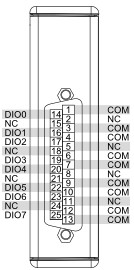
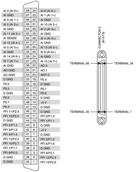
Figure 2 is an example of a device pinout for a multifunction data acquisition card, PXIe-6361. Figure 3 shows an example device pinout for one of the cDAQ modules, NI-9401.

Figure 3. NI 9401 Device Pinout.
Understanding Device or Module Mapping to Cable and Accessories
All accessories, with the exception of PXI front mounted blocks, connect to a device or module through a cable. Unless creating a custom breakout box or test fixture, it's typically unnecessary to understand the pin mapping at each cable and device connector. Instead, you can take the above information from above in regards to the signal mapping, and use that to wire to the labeled numerical screw or BNC terminals once you have connected your cable.
