Five Tips to Reduce Measurement Noise
Overview
Ensuring measurement accuracy often means going beyond reading raw specifications in a data sheet. Understanding an application in the context of its electrical environment is also important for securing success, particularly in a noisy or industrial setting. Electronic noise, measured as noise voltage, refers to unexpected electrical signals generated by ground loops, high common-mode voltages, electromagnetic radiation, thermal noise, and other electronic phenomena. Noise voltage is expressed as nanovolts per root hertz (nV/√Hz) when referring to noise density across a frequency spectrum, indicating the amount of noise voltage per unit bandwidth. Electronic noise can make accurate signal measurements difficult or impossible.
There are many techniques for reducing noise in a measurement system, which include proper shielding, cabling, and termination. Beyond these common best practices, however, there is more you can do to ensure better noise immunity and signal integrity. The following five techniques serve as guidelines for achieving more accurate measurement results.
Contents
- Reject DC Common-Mode Voltage
- Reject AC Common-Mode Voltage
- Break Ground Loops
- Use 4-20 mA Current Loops
- Use 24 V Digital Logic
- Conclusion
Reject DC Common-Mode Voltage
Making highly accurate measurements often starts with differential readings. An ideal differential measurement device reads only the potential difference between the positive and negative terminals of its instrumentation amplifier(s). Practical devices, however, are limited in their ability to reject common-mode voltages. Common-mode voltage is the voltage common to both the positive and negative terminals of an instrumentation amplifier. In Figure 1, 5 V is common to both the AI+ and AI- terminals, and the ideal device reads the resulting 5 V difference between the two terminals.
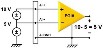
The maximum working voltage of a data acquisition (DAQ) device refers to the signal voltage plus the common-mode voltage and specifies the largest potential that may exist between an input and earth ground. The maximum working voltage for most DAQ devices is the same as the input range of the instrumentation amplifier. For example, the PCIe-6320 device has a maximum working voltage of ±11 V; no input signal can exceed 11 V without causing damage to the amplifier.
Isolation can dramatically increase the maximum working voltage of a DAQ device. In the context of a measurement system, “isolation” means physically and electrically separating two parts of a circuit. An isolator passes data from one part of the circuit to another without conducting electricity. Because current cannot flow across this isolation barrier, you can level-shift the DAQ device ground reference away from earth ground. This decouples the maximum working voltage specification from the input range of the amplifier. For example, in Figure 2 the instrumentation amplifier ground reference is electrically isolated from earth ground.
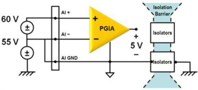
While the input range is the same as that in Figure 1, the working voltage has been extended to 60 V, rejecting 55 V of common-mode voltage. The maximum working voltage is now defined by the isolation circuitry instead of the amplifier input range.
Fuel cell testing is an example application that requires high DC common-mode voltage rejection. Each individual cell may generate approximately 1 V, but a stack of cells may produce several kilovolts or more. To accurately measure the voltage of a single 1 V cell, the measurement device must be able to reject the high common-mode voltages generated by the rest of the stack.
Reject AC Common-Mode Voltage
Rarely do common-mode voltages consist of only a DC level. Most sources of common-mode voltage contain an AC component in addition to a DC offset. Noise is inevitably coupled onto a measured signal from the surrounding electromagnetic environment. This is particularly troublesome for low-level analog signals passing through the instrumentation amplifier on a DAQ device.
Sources of AC noise may be broadly classified by their coupling mechanisms – capacitive, inductive, or radiative. Capacitive coupling results from time-varying electric fields, such as those created by nearby relays or other measurement signals. Inductive or magnetically coupled noise results from time-varying magnetic fields, such as those created by nearby machinery or motors. If the electromagnetic field source is far from the measurement circuit, such as with fluorescent lighting, the electric and magnetic field coupling is considered combined electromagnetic or radiative coupling. In all cases, a time-varying common-mode voltage is coupled onto the signal of interest, most often in the range of 50-60 Hz (power-line frequency).
An ideal measurement circuit has a perfectly balanced path to both the positive and negative terminals of an instrumentation amplifier. Such a system would completely reject any AC-coupled noise. A practical device, however, specifies the degree to which it can reject common-mode voltage with a common-mode rejection ratio (CMRR). The CMRR is the ratio of the measured signal gain to the common-mode gain applied by the amplifier, as noted by the following equation:
Choosing a DAQ device with a better CMRR over a broader range of frequencies can make a significant difference in your system’s overall noise immunity. Any application may benefit from rejecting 60 Hz noise. However, those with large rotating machinery or motors require noise immunity at higher frequencies.
Break Ground Loops
Ground loops are arguably the most common source of noise in data acquisition systems. Proper grounding is essential for accurate measurements, yet it is a frequently misunderstood concept. A ground loop forms when two connected terminals in a circuit are at different ground potentials. This difference causes a current to flow in the interconnection, which can produce offset errors. Further complicating matters, the voltage potential between signal source ground and DAQ device ground is generally not a DC level. This results in a signal that reveals power-line frequency components in the readings. Consider the simple thermocouple application in Figure 4.
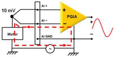
Here, an otherwise straightforward temperature measurement is complicated by the device under test (DUT) being at a different ground potential than that of the DAQ device. Though both devices share the same building ground, the difference in ground potential could be 200 mV or more if the power distribution circuits are not properly connected. The difference appears as a common-mode voltage with an AC component in the resulting measurement.
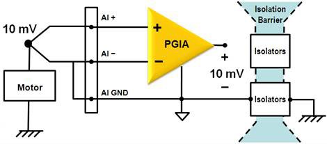
Recall that isolation is a means of electrically separating signal source ground from the instrumentation amplifier ground reference (see Figure 5).
Figure 5: Isolation eliminates ground loops by separating earth ground from the amplifier ground reference.
Because current cannot flow across the isolation barrier, the amplifier ground reference can be at a higher or lower potential than earth ground. You cannot inadvertently create a ground loop with this circuit. Using an isolated measurement device removes the ambiguity of properly grounding a measurement system, ensuring more accurate results.
Use 4-20 mA Current Loops
Long cable lengths and the presence of noise in industrial or electrically harsh environments can make accurate voltage measurements difficult. As a result, industrial transducers that sense pressure, flow, proximity, and so on often emit current signals instead of voltage. A 4-20 mA current loop is a common method of sending sensor information over long distances in many process-monitoring applications, as shown in Figure 6.
Figure 6: An instrumentation amplifier uses a shunt resistor to convert process current signals into voltage.
Each of these current loops contains three components – a sensor, a power source, and one or more DAQ devices. The current signal from the sensor is typically between 4 and 20 mA, with 4 mA representing the lowest signal value and 20 mA representing the maximum. This transmission scheme has the advantage of using 0 mA to indicate an open circuit or bad connection. Power supplies are typically in the range of 24 to 30 VDC, depending on the total amount of voltage dropped along the circuit. Finally, the DAQ device uses a high-precision shunt resistor between the leads of the instrumentation amplifier to convert the current signal into a voltage measurement. Because all the current that flows from one lead of the power supply must return to the other, current loop signals are immune to most sources of electrical noise and voltage (IR) drops along extensive cable lengths. Furthermore, the leads that provide power to the sensor also carry the measurement signal, greatly simplifying field wiring.
An isolation barrier such as the one shown in Figure 6 provides two main benefits in current loop applications. First, because power supply voltages typically exceed the maximum input range of most instrumentation amplifiers, isolation is essential for level-shifting the amplifier ground away from earth ground to an acceptable voltage. Second, current loops operate on the principal that current never leaves the circuit. Therefore, isolating the current loop from any path to ground prevents degradation of the signal. Some DAQ devices provide a built-in shunt resistors and up to 60 VDC of isolation from earth ground for 4-20 mA current loop applications.
Use 24 V Digital Logic
Measurement noise is not limited to analog signals. Digital logic may also be affected by a noisy electrical environment, possibly indicating false on/off values or accidental triggers. There are many voltage levels and logic families associated with digital I/O, some more noise resistant than others. Transistor-transistor logic (TTL) is by far the most common logic family, powering everything from microprocessors to LEDs. Though it is widely available, TTL may not always be the best choice for all digital applications.
For industrial applications, TTL has the inherent disadvantage of small noise margins. With high- and low-logic levels of 2.0 V and 0.8 V, respectively, there is little room for error. For example, the low-level noise margin for a TTL input is 0.3 V (the difference between 0.8 V, the maximum low-level TTL input, and 0.5 V, the maximum low-level TTL output). Any noise coupled to the digital signal in excess of 0.3 V may shift the voltage into the undefined region between 0.8 V and 2.0 V. Here, the behavior of the digital input is uncertain and may produce incorrect values (see Figure 7).
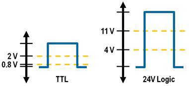
24 V logic, however, offers increased noise margins and better overall noise immunity. Because most industrial sensors, actuators, and control logic already operate off 24 V power supplies, it is convenient to use the corresponding digital logic levels. With a low-level input of 4 V and a high-level input of 11 V, the digital signals are less susceptible to noise.
Most measurement devices with 24 V digital I/O capability offer additional noise-reducing features. For example, NI industrial DIO devices have programmable input filters for debouncing relay inputs. When a mechanical relay closes, there is a short period of time (on the order of milliseconds) during which the contact surfaces bounce against each other. Without filtering, the logic input may read this as a burst of on/off signals. These devices also offer isolation, an important factor to consider if parts of the overall system are powered from different supplies.
Conclusion
There are many factors to consider when attempting to reduce noise in a measurement system. Beyond proper shielding, cabling, and termination, careful consideration of common-mode voltages, grounding, and nearby noise sources is essential for accurate results. However, understanding the electrical environment of your system is not always straightforward. Isolation is an easy means of adding another layer of confidence to your measurements, no matter the signal or application.

