Grounding Guide for Test and Measurement Devices
Overview
Contents
- Introduction
- Definitions
- Grounding for Facilities
- Grounding of Test and Measurement Equipment for EMC
- Additional Resources
Introduction
This article provides general guidelines for installing National Instruments test and measurement equipment that require a connection to the facility grounding system for the purpose of enhancing electromagnetic compatibility (EMC) performance in accordance with the product documentation.
Caution: Local electrical codes typically specify requirements for connecting equipment to the grounding electrode system of a facility. Ensure that your installation complies with all applicable safety requirements. When in doubt, contact a licensed electrician to perform the installation.
Definitions
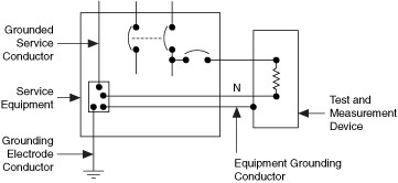
- Equipment grounding conductor: The conductor used to connect the noncurrent-carrying metal parts of equipment, cable shields, and other metal enclosures to the system grounded conductor, the grounding electrode conductor, or both, at the service equipment.
- Ground: A conducting connection, whether intentional or accidental, between an electrical circuit or equipment and the earth, or to some conducting body that serves in place of the earth.
- Grounded: Connected to earth or to some conducting body that serves in place of the earth.
- Grounding conductor: A conductor used to connect equipment or the grounded circuit of a wiring system to a grounding electrode or electrodes.
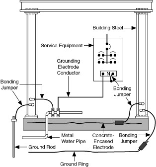
- Grounding electrode: A device that establishes an electrical connection to the earth.
- Grounding electrode conductor: The conductor used to connect the equipment grounding conductor or the grounded conductor to the grounding electrode.
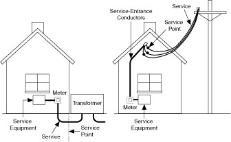
- Service: The conductors and equipment used for delivering electrical energy from the serving utility to the wiring system of the premises served.
- Service equipment: The necessary equipment, usually consisting of circuit breaker(s) or switch(es) and fuse(s) and their accessories, connected to the load end of service conductors to a building or other structure and intended to constitute the main control and cutoff of the supply.
- Service point: The point of connection between the facilities of the service utility and the premises wiring.
Grounding for Facilities
The purpose of establishing a circuit or system grounding in facilities is to:
- Limit excessive voltage from line surges, crossovers with higher voltage lines, and lightning and/or
- Keep noncurrent-carrying enclosures and cable shields at a common potential.
This document employs the second purpose—to improve EMC performance.
Examples of a typical electrical service are shown in Figure 1. The service connects to the facility wiring at the service point. Connection is made to a meter, then the service equipment.
Figure 1. Example Electrical Services
The grounding rod and any other grounding electrodes for a particular facility, shown in Figure 2, are bonded together to form the grounding electrode system. This grounding electrode system is at earth-ground potential and is the central ground for all electrical equipment and AC power within any facility. The grounding electrode system is connected to the neutral terminal bar in the service panel, or other service equipment, using the grounding electrode conductor. The neutral terminal bar is used as the reference for the mains neutral (white) conductor, the safety ground (green) conductor, and the equipment grounding conductor(s).
Figure 2. Example Grounding Electrode System
Grounding of Test and Measurement Equipment for EMC
When required by the National Instruments product documentation or as required for the particular installation, the chassis of the product should be connected to the grounding electrode system using an equipment grounding conductor as shown in Figure 3. Connect the ground lug of the test and measurement device to the grounding electrode system of your facility through an equipment grounding conductor of 14 AWG or larger stranded, copper wire.
Figure 3. Grounding of Test and Measurement Devices


