Graphical System Design Basics: Accelerating Development Time and Bringing Embedded Design to the Masses
Overview
Graphical system design is a revolutionary approach to solving design challenges that blends intuitive graphical programming and flexible commercial-off-the-shelf (COTS) hardware to help engineers and scientists more efficiently design, prototype, and deploy embedded systems. Using the graphical system design approach will enable you to use a single environment across all stages of design to increase productivity, save money and bring embedded technology to the domain expert.
Contents
- Graphical Programming for Embedded Design
- Customizable Off-the-shelf Prototyping Platforms
- Custom Deployment Options
- Conclusion
- References
- Next Steps
Graphical Programming for Embedded Design
Many embedded systems run autonomously and need to execute many tasks in parallel with specific timing requirements. Consider a machine control system that needs to control a linear stage, rotate multiple shafts, control lighting and read in video data; in a system like this, there are multiple processes that must happen deterministically, in real-time, and in parallel. Using traditional, text-based tools such as C for these applications quickly escalates in complexity.
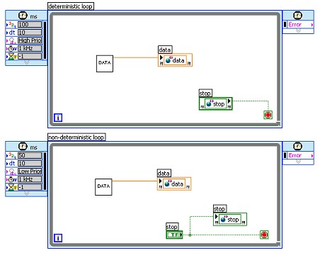
LabVIEW on the other hand, facilitates complex programming and timing models easily because of native functionality. More than twenty years ago, NI created components and technology in the form of the LabVIEW graphical development environment. LabVIEW natively incorporates timing into code using coding structures to implement timing, and representing parallelism is simply a matter of drawing another loop as shown in Figure 1.

Figure 1. Parallel Timed Loops in LabVIEW intuitively display parallel tasks.
To implement this level of timing and parallelism in text code is a barrier to a broader audience of domain experts where the graphical representation is simply much more clear and accessible to scientists and engineers. If we extended the LabVIEW paradigm to chips including FPGAs and microprocessors, you can see that LabVIEW also easily manages the parallel architecture of the silicon using the same consistency and scalability.
Another key requirement for embedded system design is that the software platform addresses the various algorithm design views common in real-time embedded design. Dr. Edward Lee, a leading researcher at University of California at Berkeley for embedded software platforms, refers to the various design views as models of computation [3]. These models of computation match the way system designers view their system to help minimize the complexity of translating system requirements into a software design.
Over the last several years LabVIEW has expanded to incorporate multiple models of computation to better meet the needs of embedded system designers and their varied skill sets. LabVIEW now includes text-based math, continuous time simulation, state diagrams, and graphical dataflow models to represent a variety of algorithms. LabVIEW also includes interactive tools to enhance the design experience for digital filters, control models, and digital signal processing algorithms to further ease designs in these vertical applications. Now, let’s look at how you can implement these algorithms on to flexible COTS hardware platforms to significantly decrease your time to first prototype.
Customizable Off-the-shelf Prototyping Platforms
As previously mentioned, with the many designs that are late or never released to market or worse, designs failing after release, something needs to be done to get more high-quality products out sooner. One way to address both of those issues is to prototype the systems better by integrating real world signals and real hardware into the design process sooner so that high-quality designs are iterated on and problems are found (and fixed) earlier.
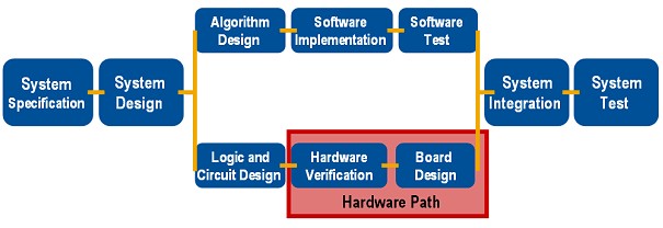
Looking at the design flow in Figure 2, LabVIEW can already combine algorithm design and logic design using the LabVIEW FPGA Module that targets LabVIEW designs to FPGAs on NI hardware. Let’s now focus on the hardware path to look for efficiencies and ways to shorten the process.

Today, if you are creating custom hardware for final deployment, it is difficult to have the software and hardware developed in parallel as the software is never tested on representative hardware until the process reaches the system integration step. Additionally, you do not want the software development to be purely theoretical, because waiting until the system integration test to include I/O and test the design with real signals may mean that you discover problems too late to meet design deadlines.
Most designers currently use a solution like an evaluation board to prototype their systems. However, these boards often only include a few analog and digital I/O channels and rarely include vision, motion, or ability to synchronize I/O. Additionally, designers often have to waste time developing custom boards for sensors or specialized I/O, just to complete a proof of concept.
Using flexible COTS prototyping platforms instead can truly streamline this process, as shown in Figure 3, and eliminates much of the work required for hardware verification and board design. Much like PCs today, where anyone can go to an electronics store and plug components such as memory, motherboards, and peripheral together to create a PC, graphical system design strives to achieve the same standardization for prototyping platforms.

Figure 3. Stream-lined development flow with Graphical System Design
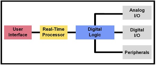
For most systems, a prototyping platform must incorporate the same components of the final deployed system. These components are often a real-time processor for executing algorithms deterministically, programmable digital logic for high-speed processing or interfacing the real-time processor to other components, and varied types of I/O and peripherals [Figure 4]. Finally, as with any system, if the off-the-shelf I/O doesn’t serve all of your needs, the platform should also be extensible and customizable when needed.

Figure 4. Typical components of an embedded system.
National Instruments offers several types of prototyping platforms including NI CompactRIO that contain all of the basic building blocks of an embedded system. The controller contains a 32-bit processor running a real-time operating system. The CompactRIO backplane contains an FPGA that can implement high-speed processing and actually configures and provides interfaces to the I/O modules which include options for analog input and output, digital input and output, and counter/timer functionally. Each of the modules includes direct connectivity to sensors and actuators as well as built-in signal conditioning and isolation. A module development kit is also available that allows developers to expand the platform to include custom modules – all plugging into this COTS framework.
Additionally, CompactRIO is industrially packaged (-40 to 70 deg C, 50 G shock) with a small footprint (3.5in x 3.5in x 7.1in) and low power requirements (7 to 10 W typical) making it ideal for not only prototyping but also deployment of in-vehicle, machine control, and on-board predictive maintenance applications.
Custom Deployment Options
As previously mentioned, CompactRIO can often be used not only for prototyping but also for deployment because of its packaging, durability and cost. However, there may be times when size or power may drive the need for smaller, custom board designs. To address that need, designers can preserve their software investment by using the LabVIEW Embedded Development Module to deploy code to any 32-bit processor.
The LabVIEW Embedded Development Module combines all of the graphical development benefits we just covered with the out-of-the-box analysis functions, integrated I/O, and interactive, graphical debugging. This module is able to target any 32-bit microprocessor and provides a framework that can openly integrate a variety of existing C-based, 3rd party tool chains and operating systems to target custom board designs. Once integrated, users can develop 100% graphically and interactively debug their application. By generating code to integrate with all existing targets in the market users can have ultimate flexibility and breadth in target options.
This new technology empowers a broader range of scientists, engineers and domain experts to design their algorithms, develop the application, program the logic, prototype the system and then deploy it to the target of choice.
Conclusion
The time has come for a new approach to electronic system design. Graphical system design brings a software platform combined with a hardware platform that offers the opportunity to significantly reduce development cost and time to market. A software platform which integrates multiple models of computation minimizes the time to implement specifications into a design. A flexible COTS hardware prototyping platform which supports the software platform and offers customizable components minimizes the time to first prototype because the time and money required for designing custom hardware is eliminated. Additionally, prototyping with real I/O results in a higher quality design – eliminating the design failures we see today. Finally, consistent graphical software from your design to your prototyping platform to your final deployment target maximizes code reuse and eases the transition to final deployment. With LabVIEW, you have a single graphical platform to design, prototype and deploy your embedded system.
References
[1] Embedded Software Development: Issues and Challenges. July 2003.
[2] http://www.techonline.com/community/related_content/21543
[3] Dr. Edward A. Lee, Advances in Computers (M. Zelkowitz, editor), Vol 56, Academic Press, London, 2002